Assembling esieabot 2024 and 2025
Inventory of parts
Image |
Description |
Image |
Description |
|---|---|---|---|
|
|
||
|
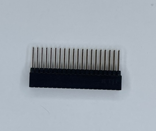
40-pin connector |
|
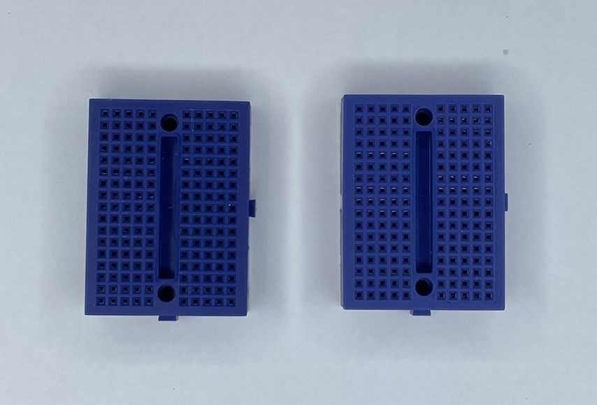
2 breadboards |
|
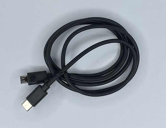
USB-C to Micro-USB cable |
|
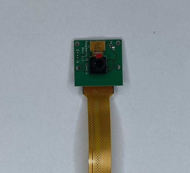
Camera with ribbon cable |
|
|
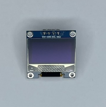
OLED screen |
|
|
|
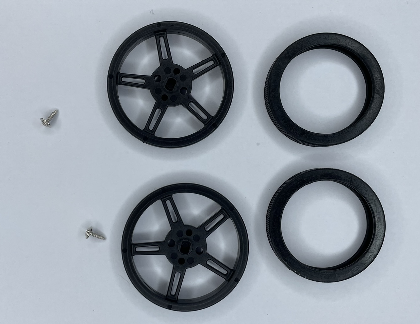
2 wheels with tires and screws |
|
|
|
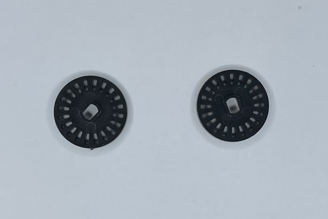
2 coded discs |
|
|
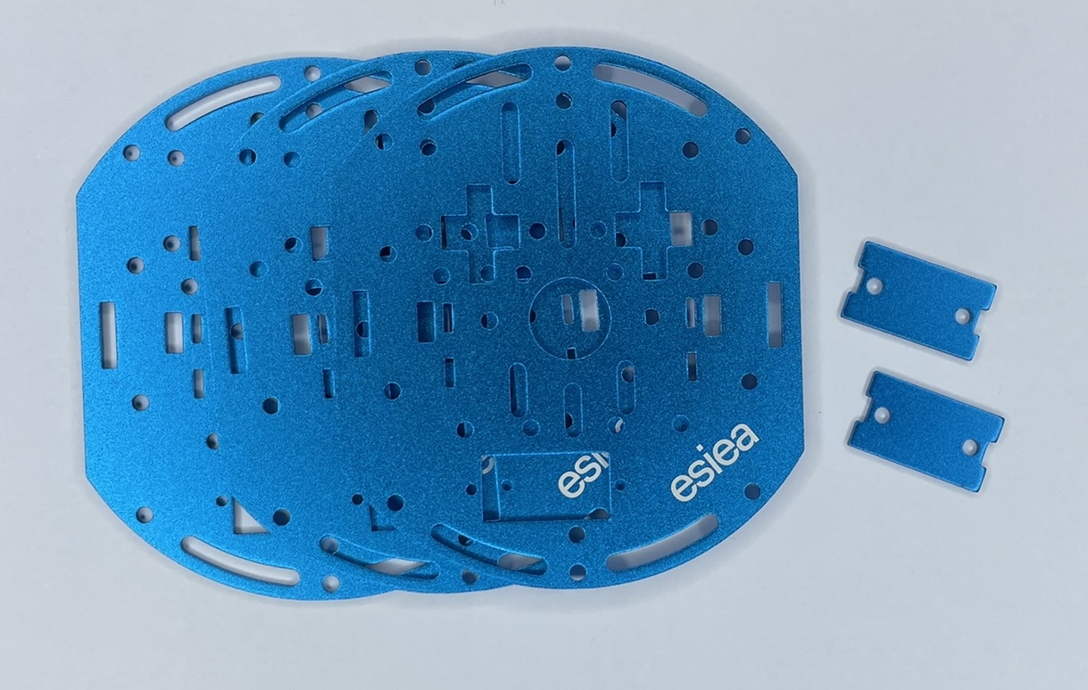
3 chassis plates and 2 motor mounts |
|
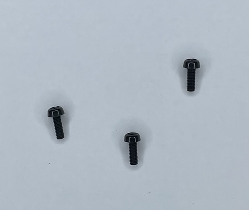
3 nylon M3 screws |
|
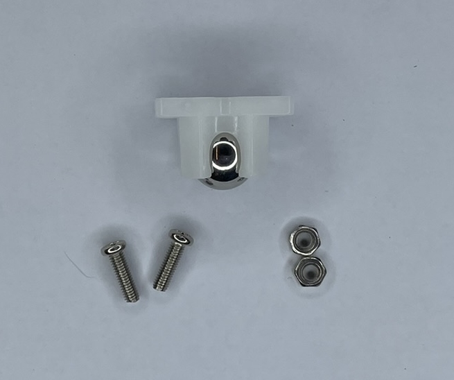
Free wheel with 2 screws and nuts |
|
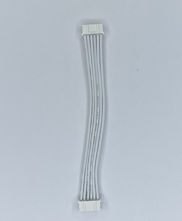
Blue or white JST cable |
|
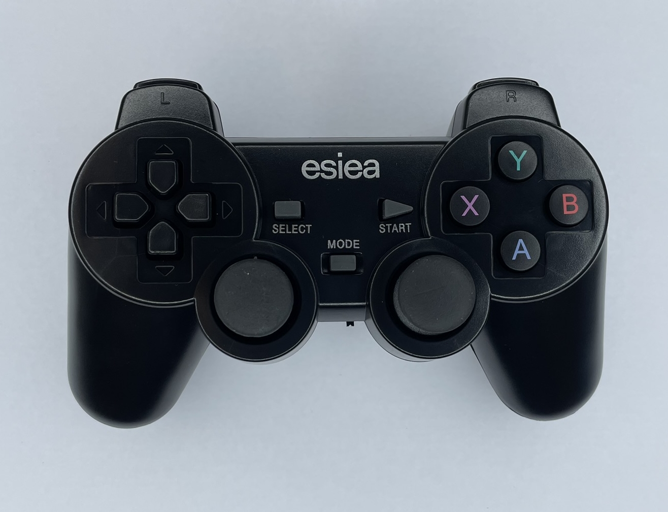
Wireless controller |
|
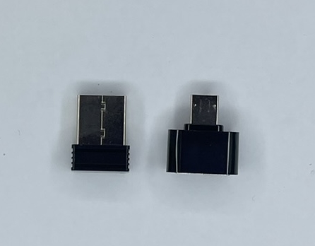
USB dongle for wireless controller and adapter |
|
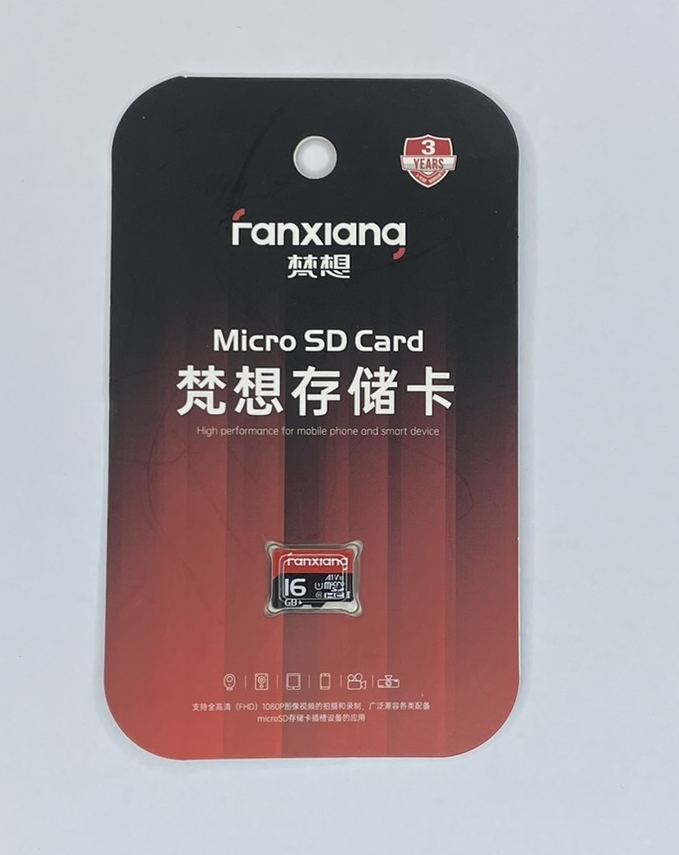
16GB micro SD card |
|
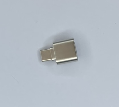
USB-C micro SD card reader |

|
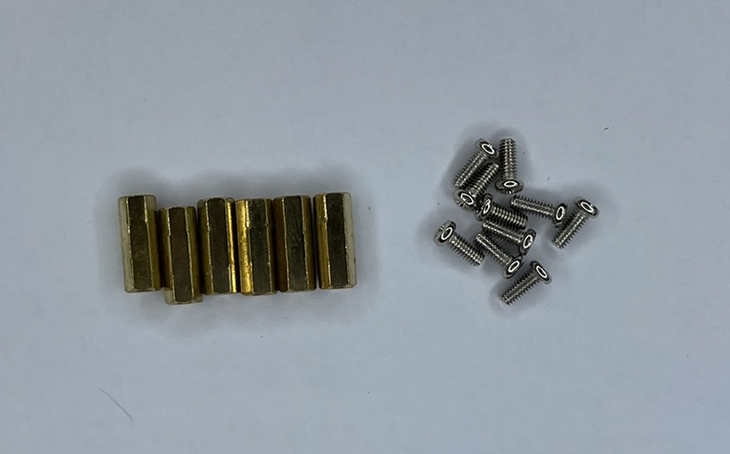
7 large M3 spacers with screws |
|
6 small M2.5 spacers with screws |
|
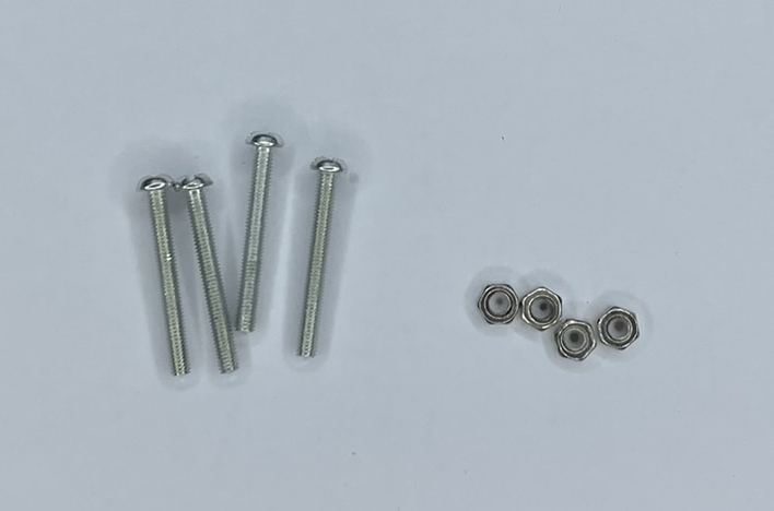
2 large M3 screws with nuts |
|
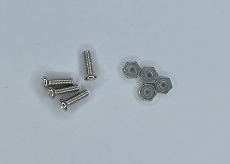
4 M2.5 screws with nuts |
|
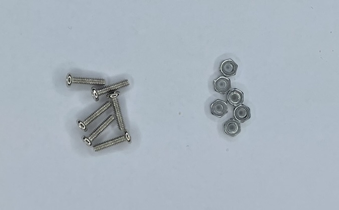
6 M2 screws with nuts |
|
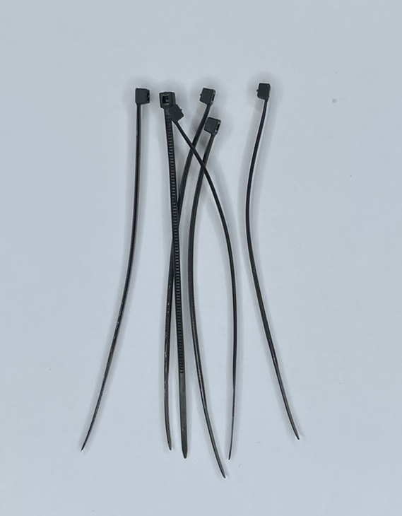
Set of cable ties |
|
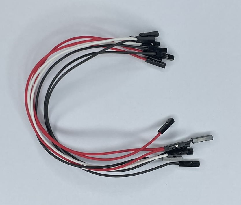
8 long female-female wires |
|
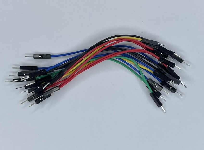
Set of male-male wires |
|
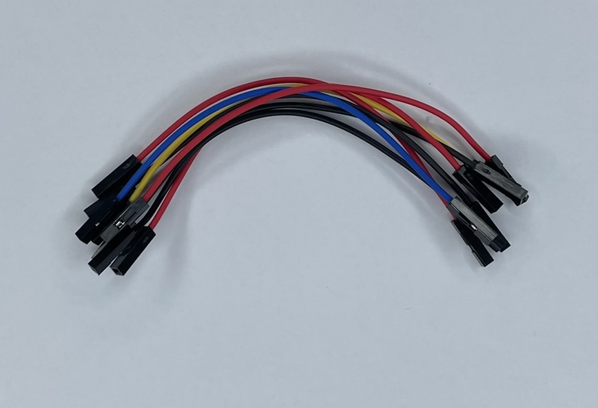
Set of female-female wires |
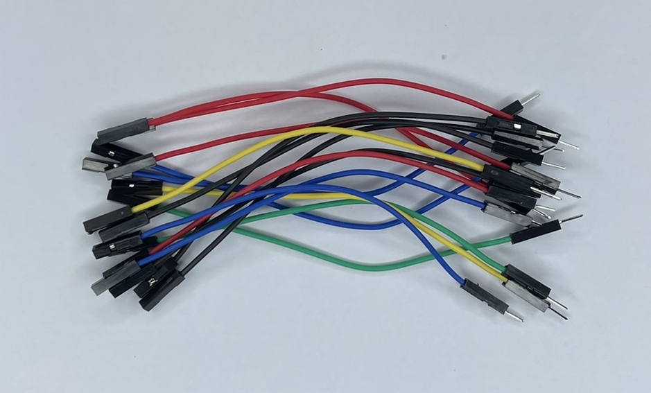
|
Set of male-female wires |
|
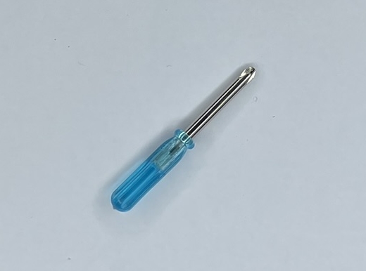
Mini screwdriver |
|
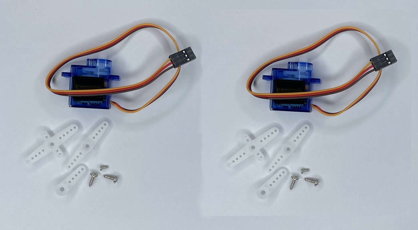
2 servo motors with accessories |
Step 0
Warning
Before starting, make sure you have all the necessary parts for assembly, refer to the parts list above.
Carefully read the text of each step, do not rely solely on the images.
It is normal to have leftover parts at the end of the assembly. Follow the steps precisely, do not add screws if they are not indicated.
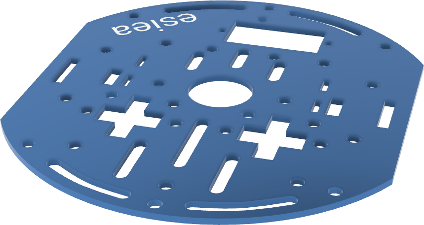
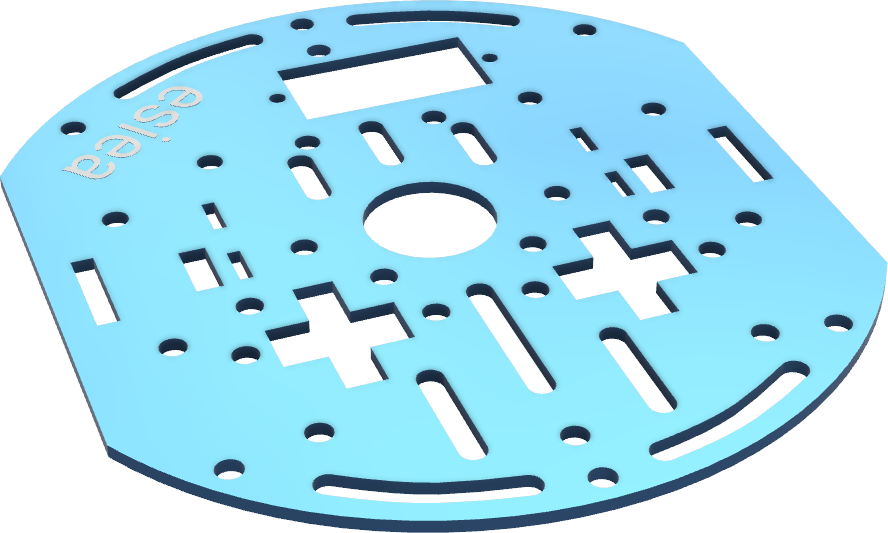
The orientation of the chassis plates is important because they are not symmetrical. Use the positioning of the ESIEA logo as a guide.
Step 1
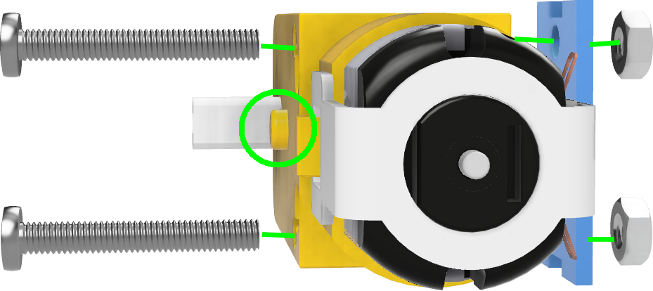
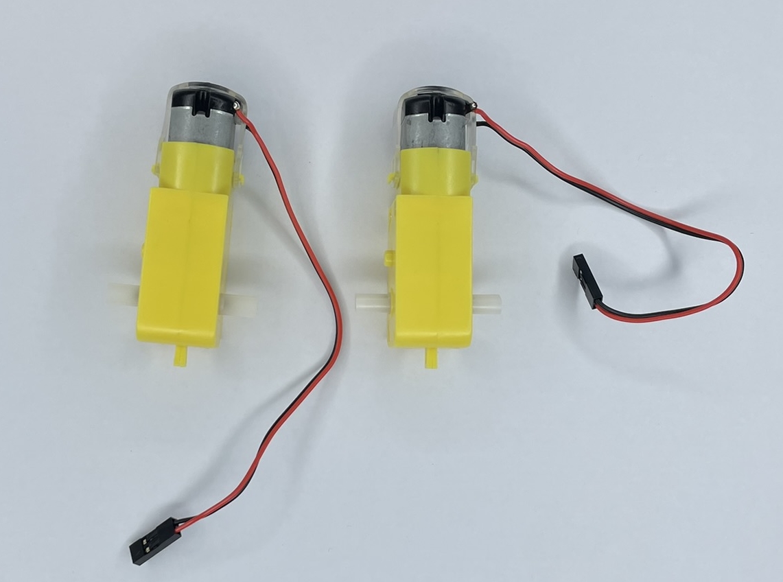
Take a motor and screw its metal support with 2 large M3 screws and their nuts.
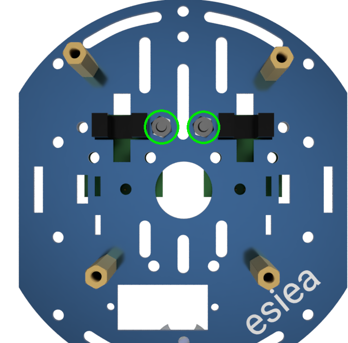
Warning
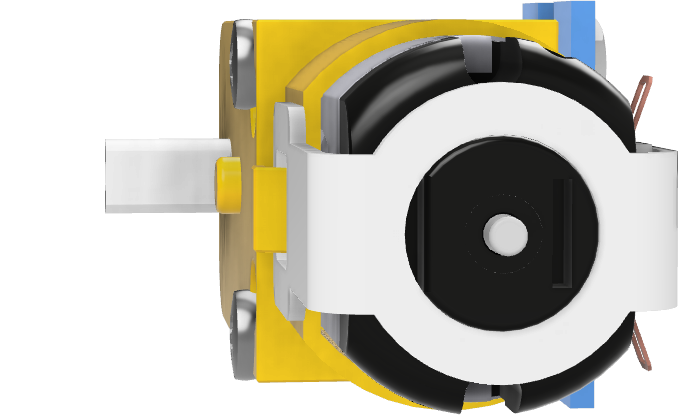
Attention, the direction of the motor is important because it is not symmetrical. To guide you, check the location of the keyway circled in the image.
Step 2
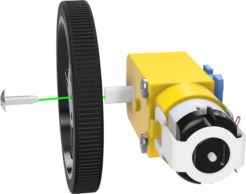
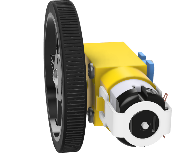
Screw the wheel and its tire to the motor using a self-tapping screw.
Step 3
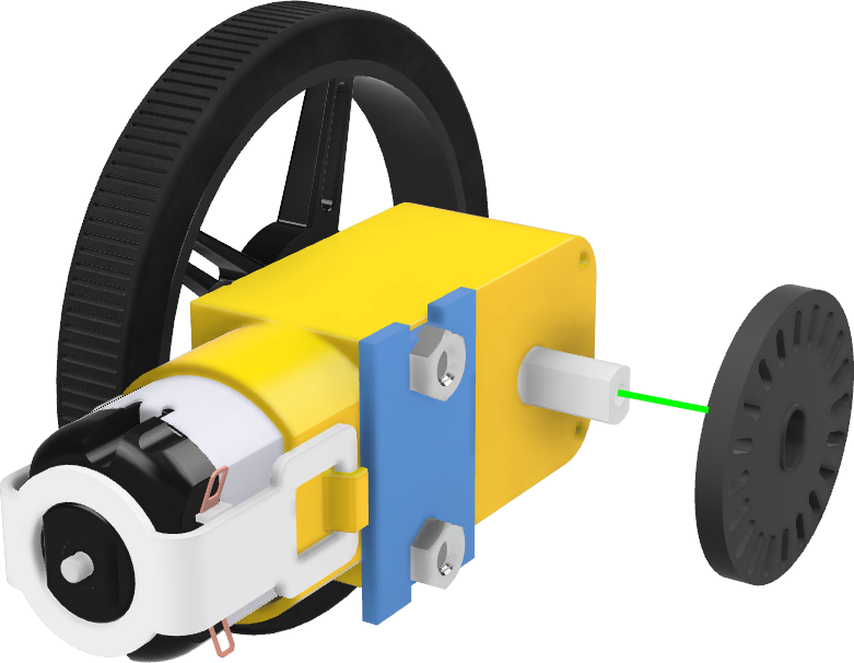
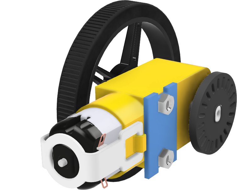
Position the speed sensor disc on the other side of the motor. The edge of the disc should reach the edge of the shaft as shown in the image.
Step 4
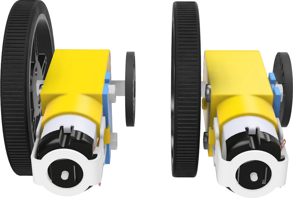
Repeat steps 1 to 3 for the second motor in exactly the same way.
Step 5
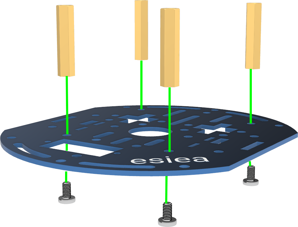
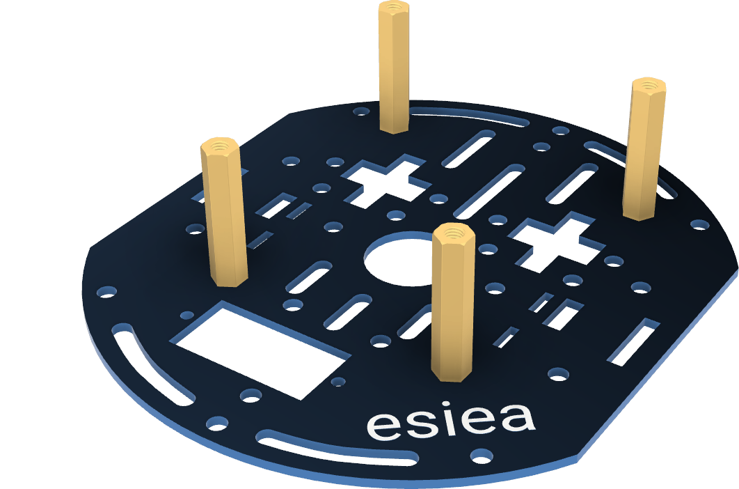
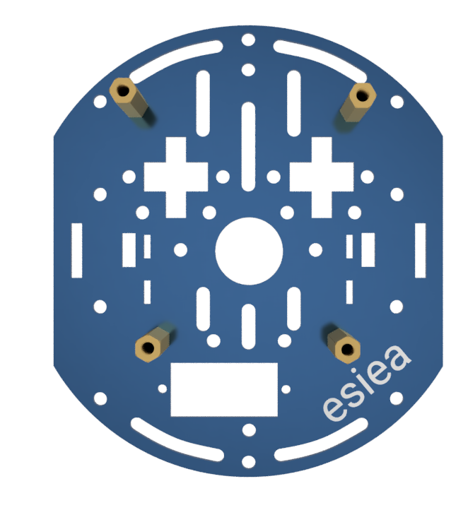
Take a chassis plate and screw 4 large M3 spacers with their respective screws at the indicated locations.
Step 6
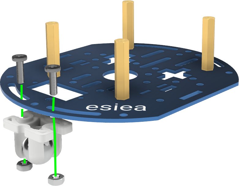
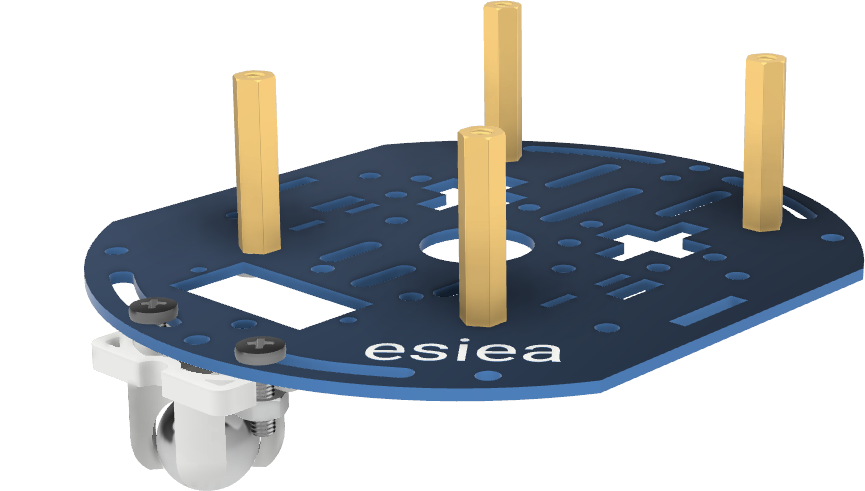
Screw the free wheel using the provided M3 screws and nuts at the indicated location.
Note
It may be easier to pre-screw the bolts onto the chassis before inserting the free wheel and tightening completely.
Step 7
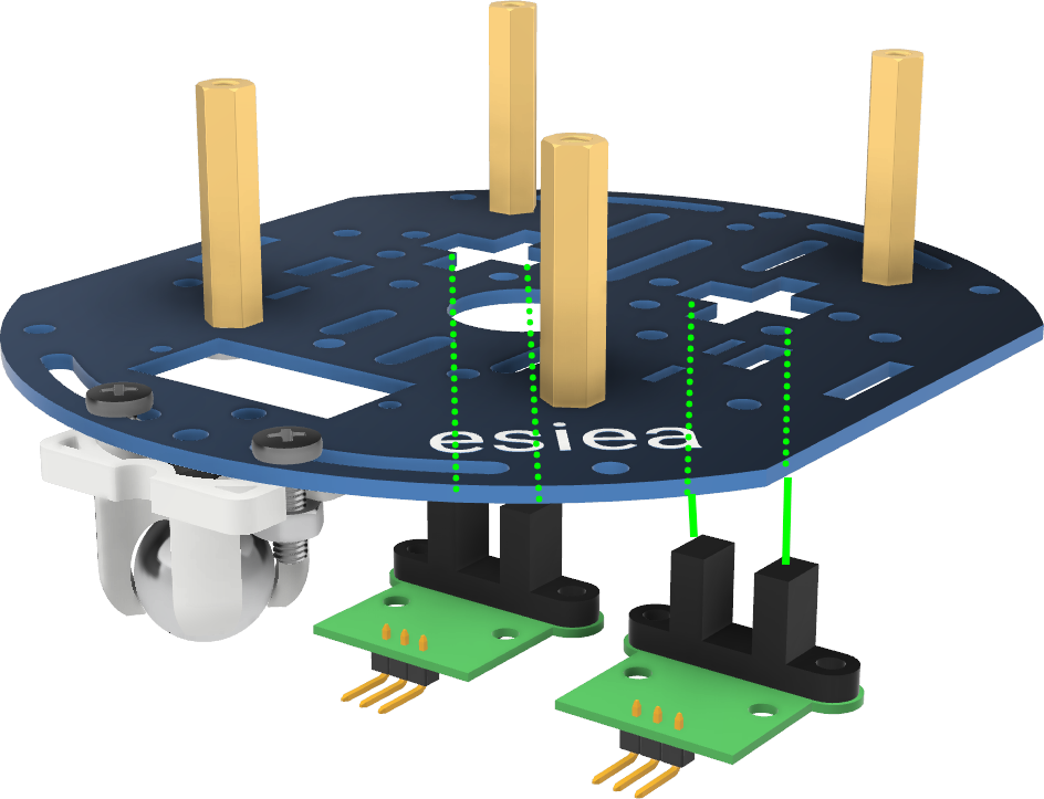
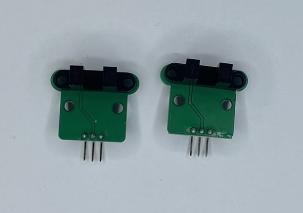
Position the speed sensors at the indicated locations on the chassis.
Step 8
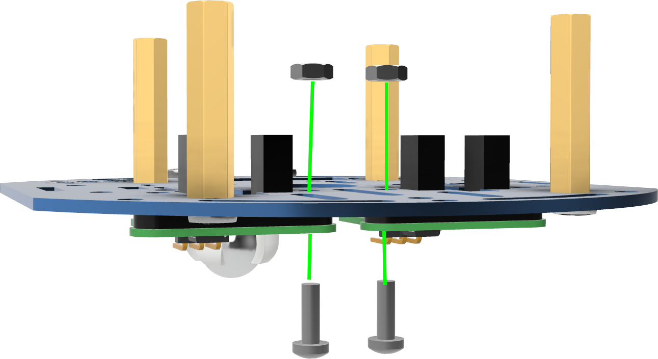
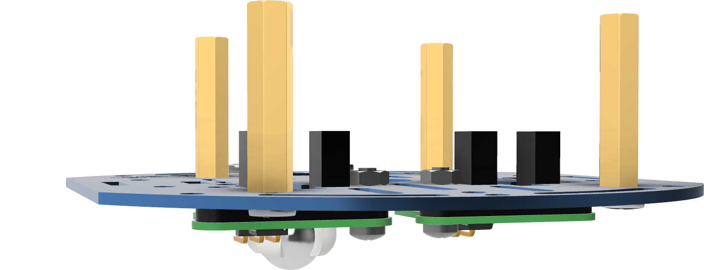
Screw the speed sensors using 2 M2.5 screws and nuts.
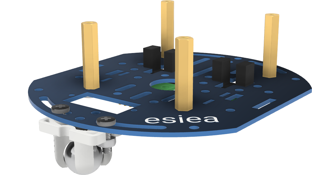
Step 9
Position the motors on the chassis at the indicated location. The metal supports of each motor should be positioned in the dedicated notches on the chassis. If necessary, you can adjust the position of the speed sensor discs so that they are well centered on the sensors.
Step 10
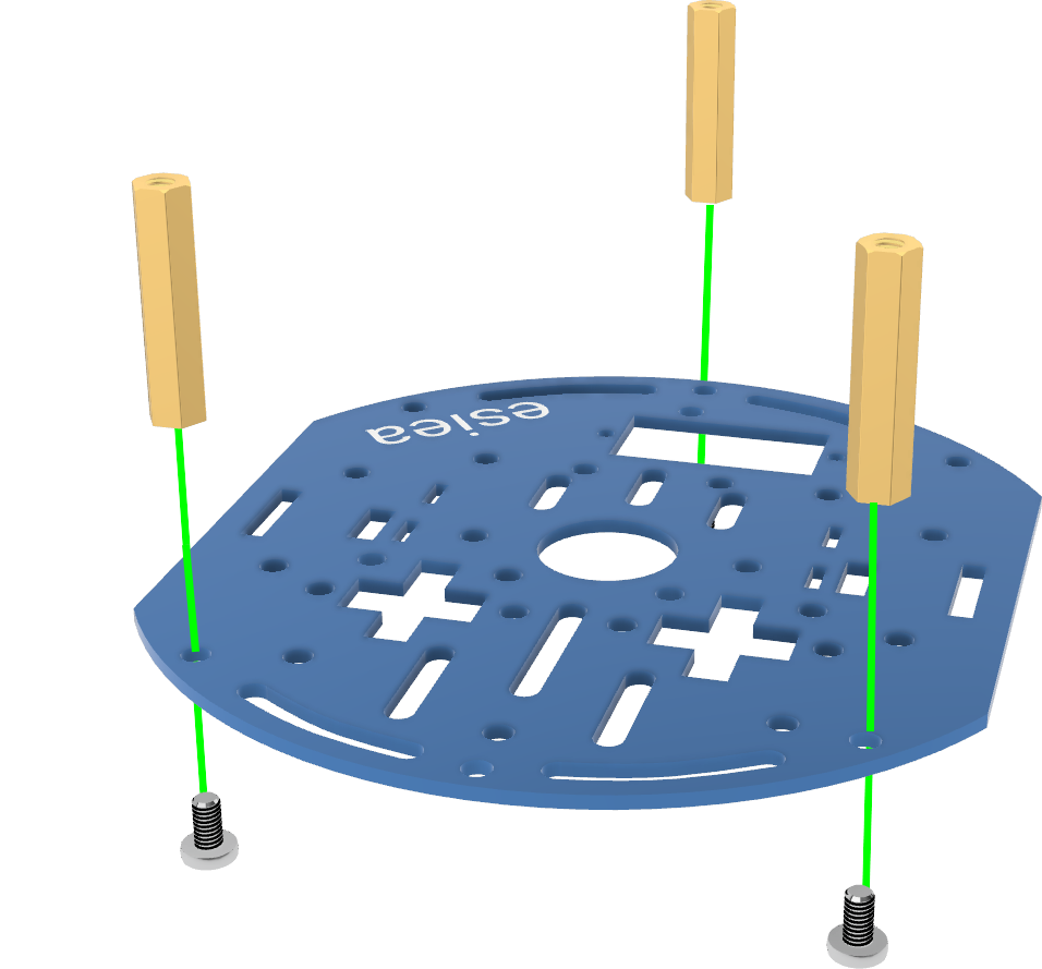
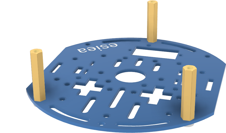
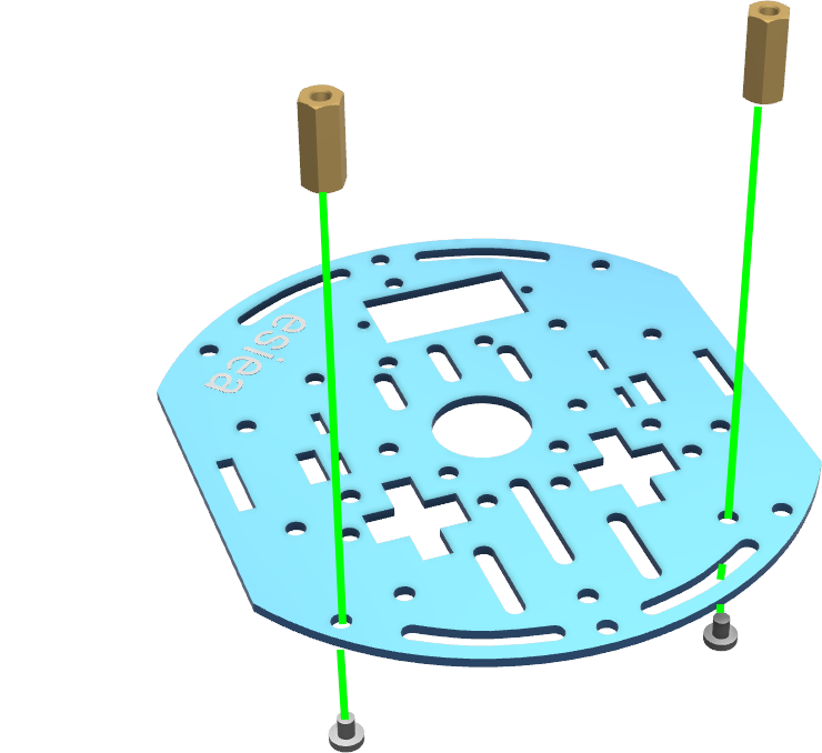
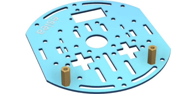
Take a new chassis plate and screw 3 large M3 spacers with their respective screws at the indicated locations.
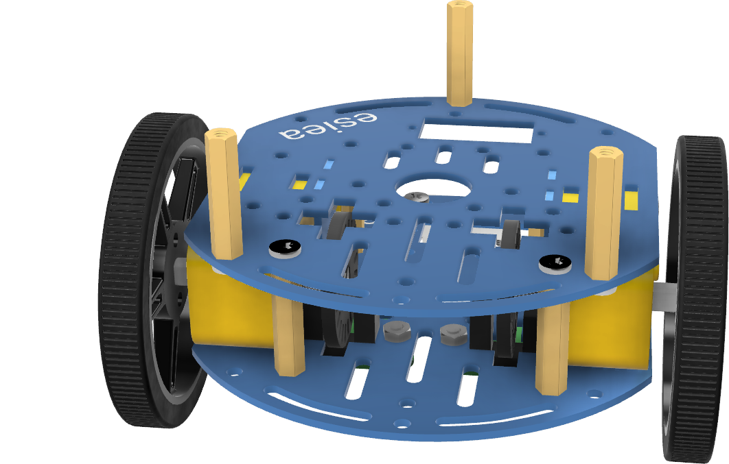
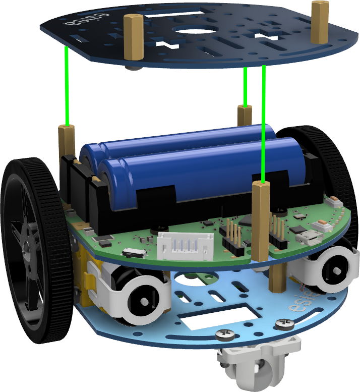
Step 11
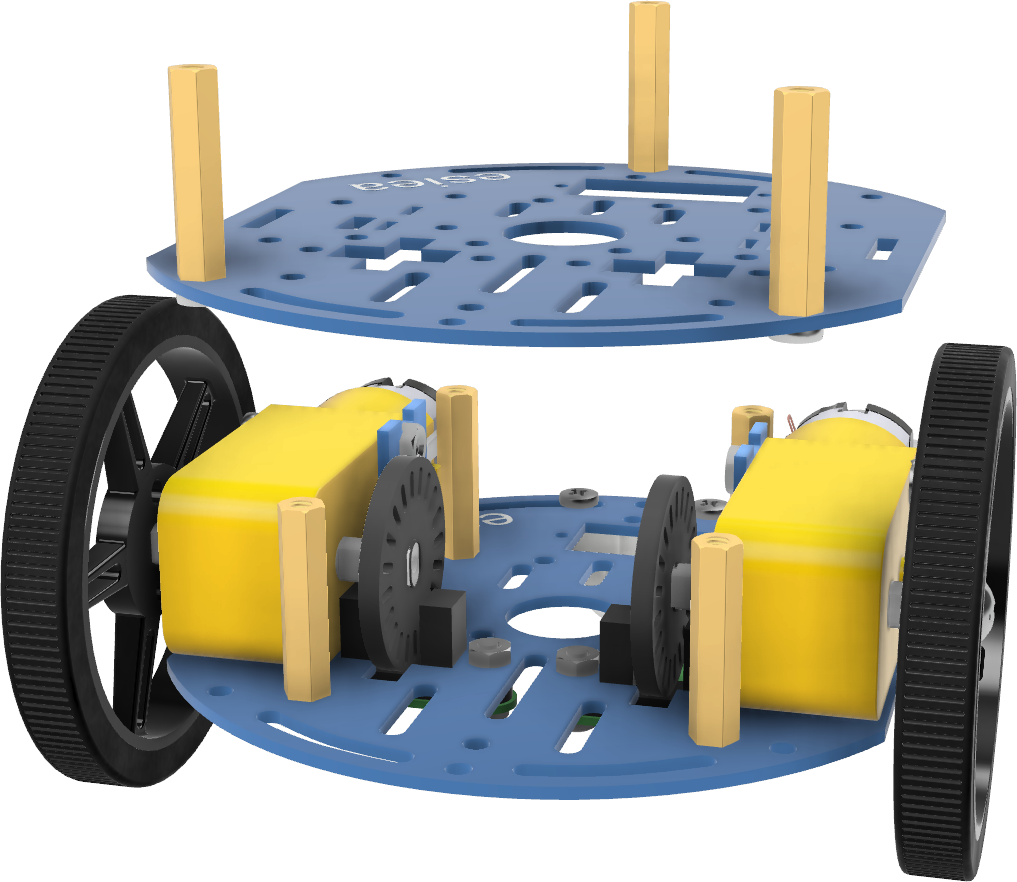
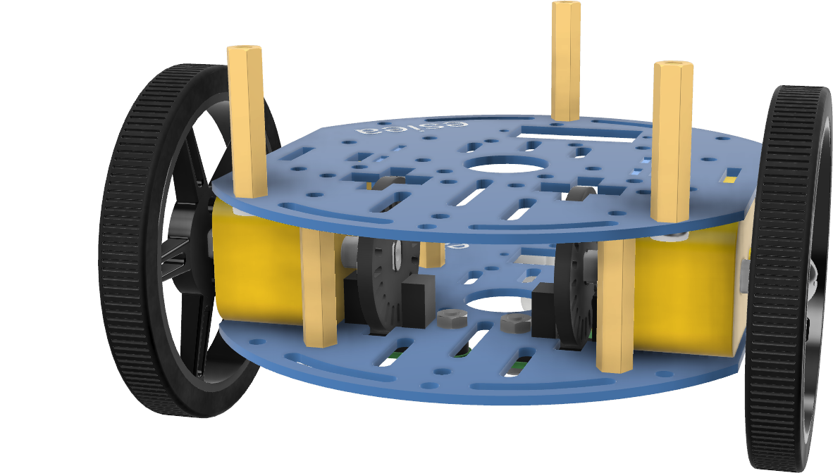
Position the new chassis plate on the previous one at the indicated location. The metal supports of the motors should again be positioned in the dedicated notches on the chassis.
Note
If necessary, you can slightly push the motors to position them correctly. It may be easier to first align one motor between the two plates and then push the second motor into position.
- width:
50%
- align:
center
Step 12
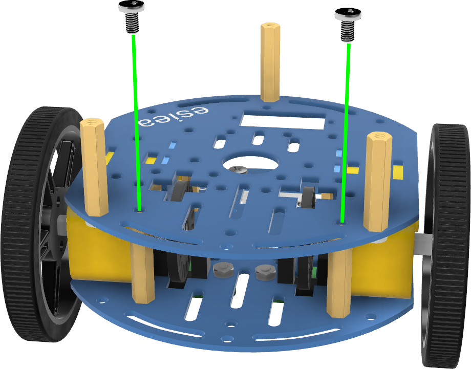
Screw the new chassis plate to the previous one using 2 M3 screws at the indicated locations.
Note
There are only 2 screws to put in, this is normal. The other 2 screws will be used to attach the power board later.
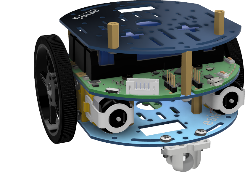
Step 13
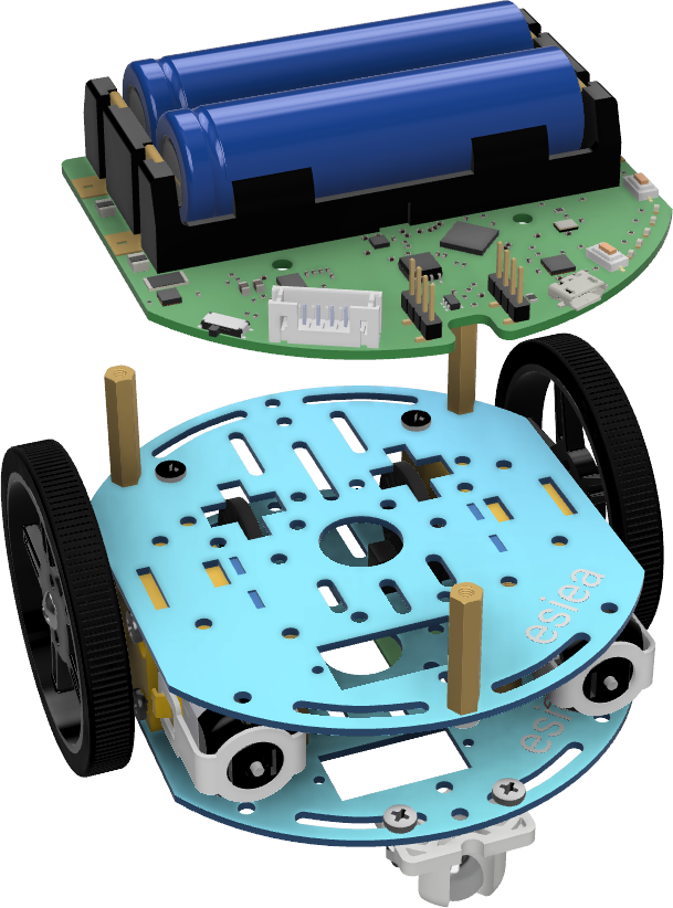
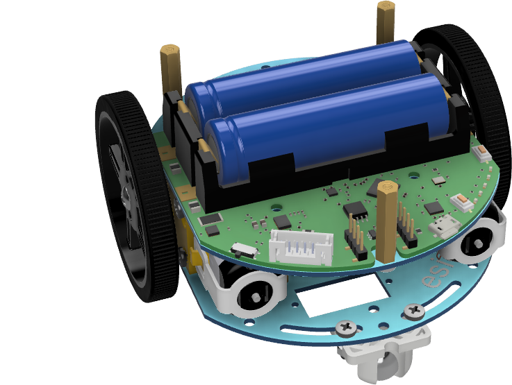
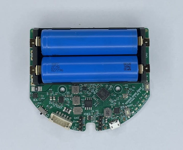
Position the power board at the indicated location.
Warning
Attention, even when turned off, the power board remains powered. Therefore, it should not come into contact with metal parts such as screws.
Step 14
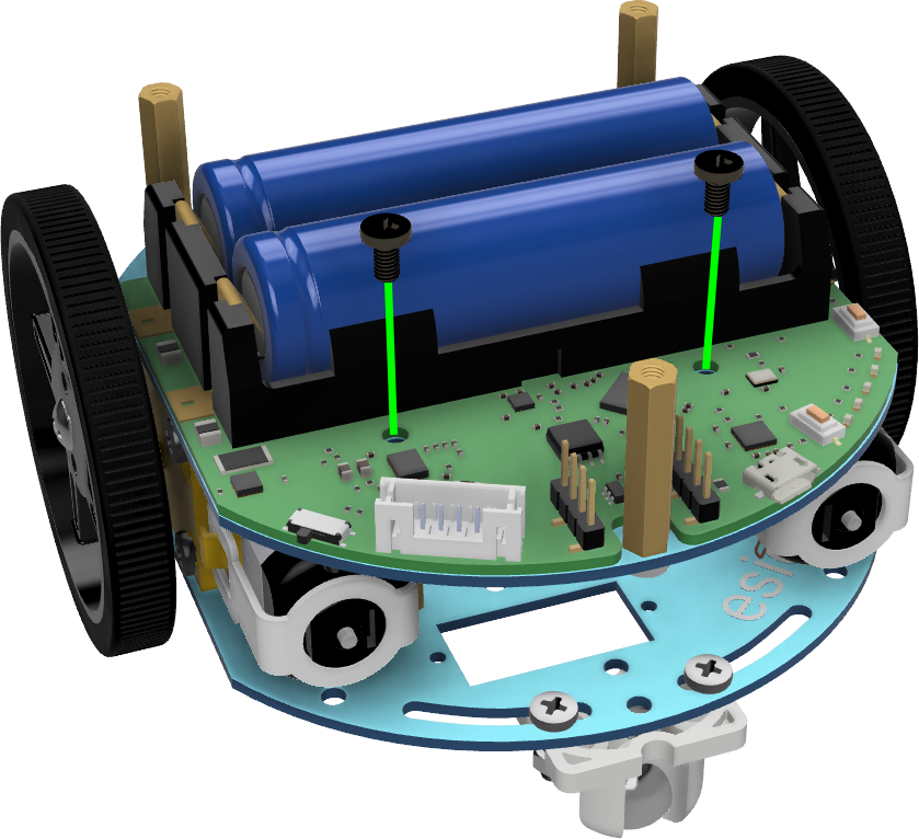
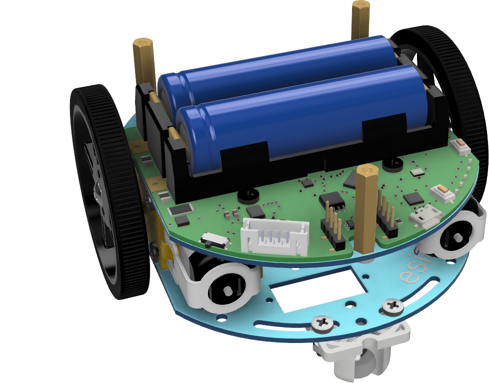
Using 2 black nylon M3 screws, screw the power board to the chassis.
Warning
Attention, as the power board remains powered even when turned off, it is important to use nylon screws to avoid any short circuit in case of accidental fall. Also, be careful that your screwdriver does not touch the components of the power board.
Note
At this step, you can also connect the JST cable to the power board to avoid having to do it later. As a reminder, this cable can be white or blue.
Step 15
Take a new chassis plate and screw 2 small M2.5 spacers with their respective screws at the indicated locations.
Warning
The position of the spacers is very important, pay attention to the orientation of the metal plate and the position of the holes.
Note
If you have a pantilt camera, you should assemble it before continuing. To do this, go to the section Assembling pantilt 2021 and 2022. You only need to follow steps 1 to 6. The connection of the servo motors will be done later on the add-on board.
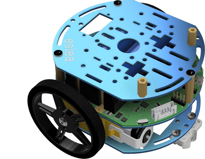
Step 16
Position this new chassis plate on the rest of the robot by aligning the spacers with the holes in the chassis.
Step 17
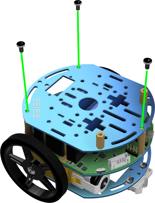
Screw the new chassis plate to the rest of the robot using 3 M3 screws at the indicated locations.
Step 18
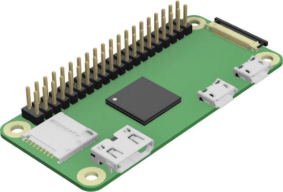
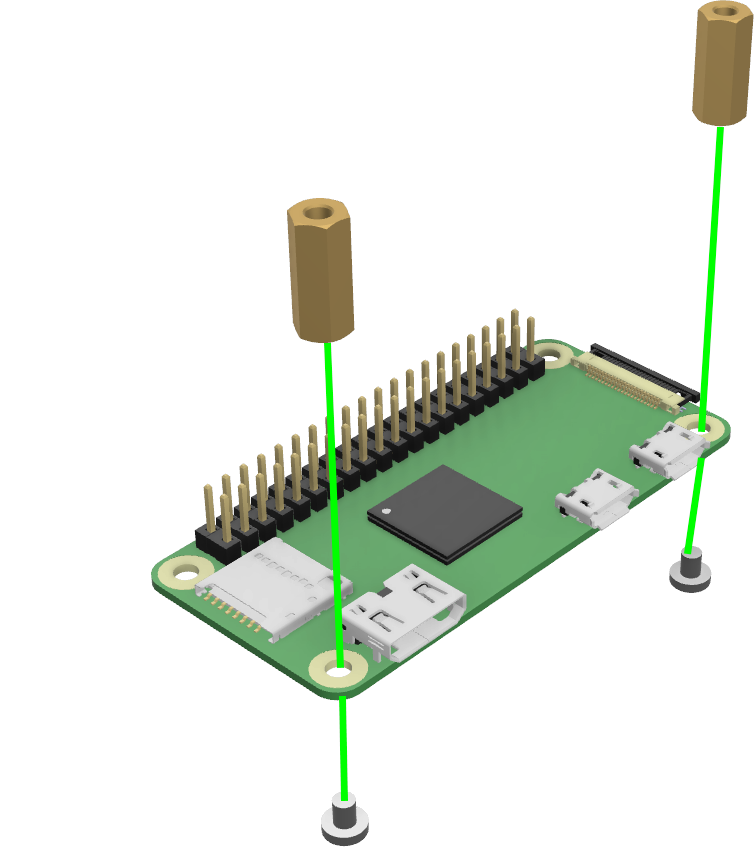
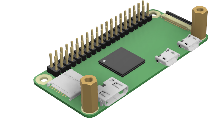
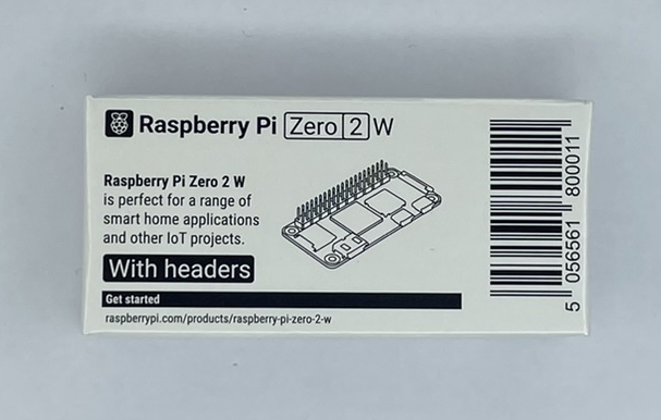
Take the Raspberry Pi Zero and screw 2 small M2.5 spacers with their respective screws at the indicated locations.
Step 19
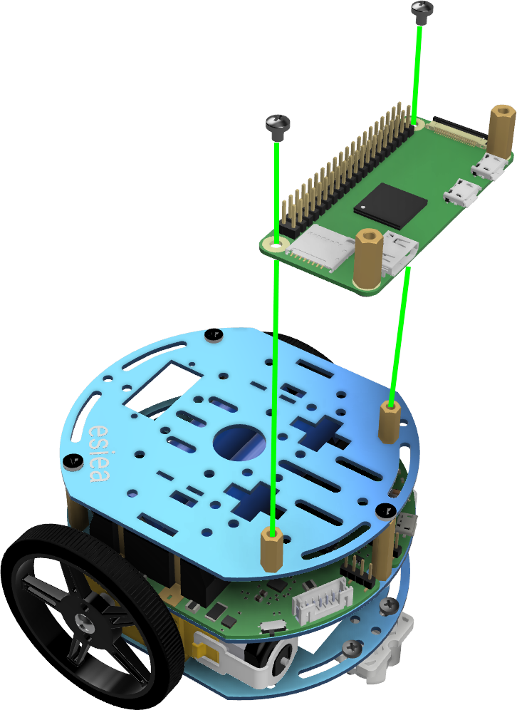
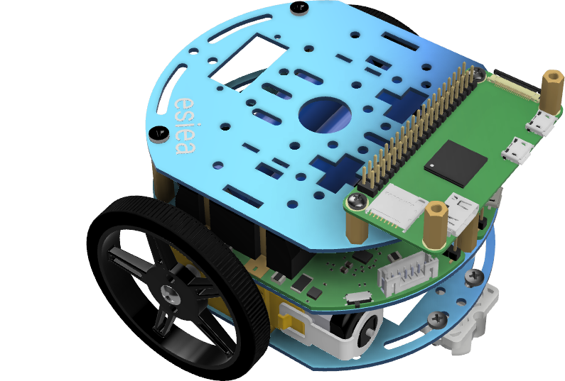
Screw the Raspberry Pi Zero onto the new chassis plate at the indicated location using 2 M2.5 screws.
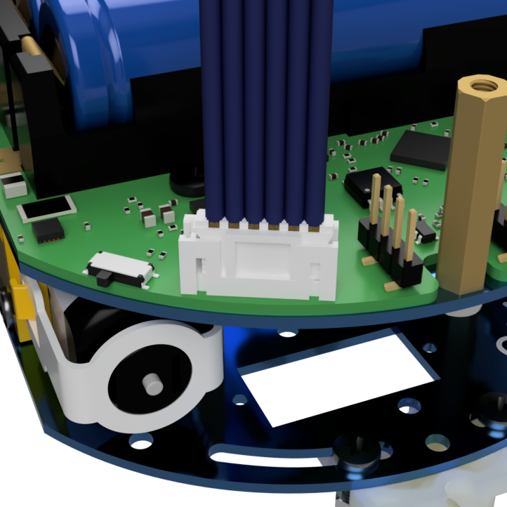
Step 20
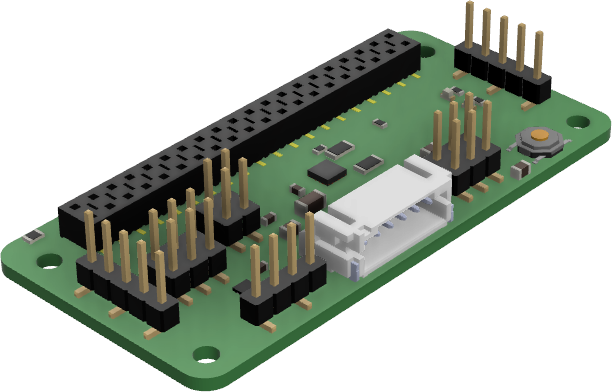
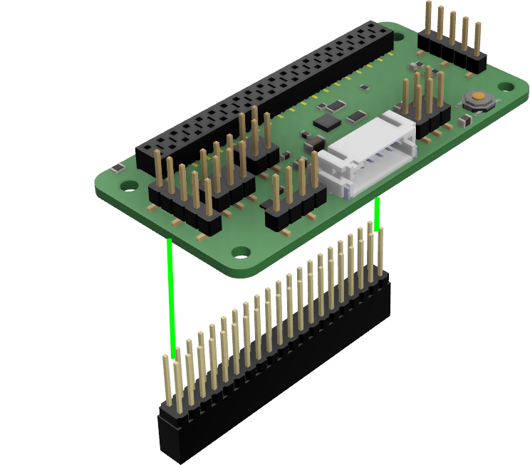
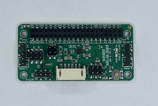
Gently insert the 40-pin connector under the add-on board at the indicated location.
Note
You should gently insert one side and then the other to facilitate assembly. Check that each small pin is properly aligned with the hole it should go into.
Warning
Attention, the connector can bend easily. It is important to handle it with care. If a pin is bent, it can be gently straightened when you insert it.
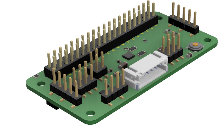
Step 21
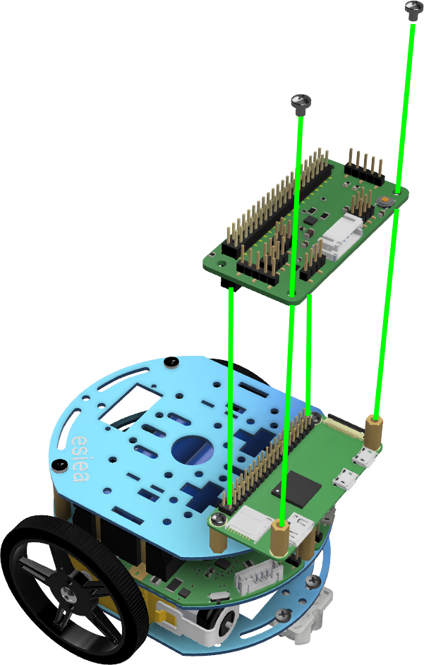
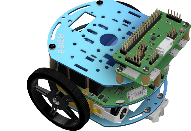
Screw the add-on board onto the Raspberry Pi Zero using 2 M2.5 screws at the indicated locations.
Step 22
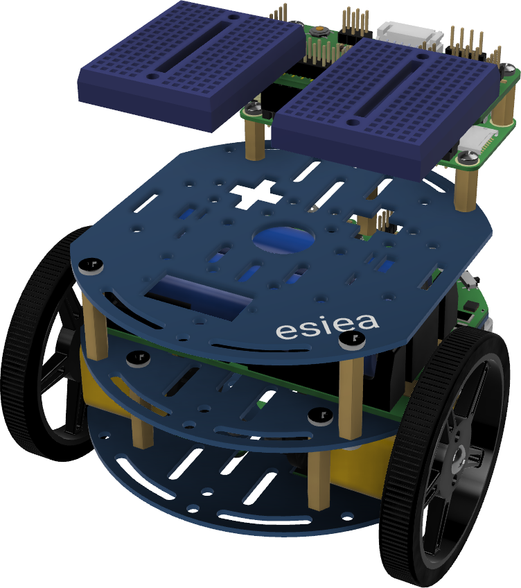
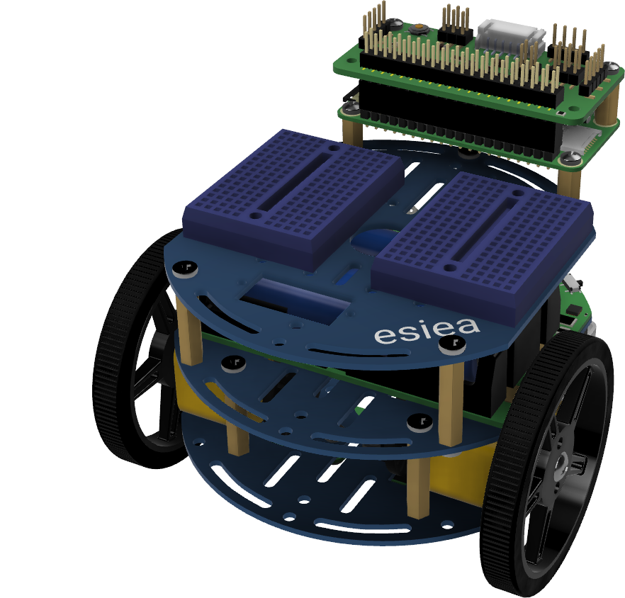
Stick two breadboards side by side on the chassis plate at the indicated location.
Note
The exact location of the breadboards does not matter. Just make sure not to cover the rectangular hole at the front of the plate.
Step 23
Connect the OLED screen to the breadboard at the indicated location.
Note
The exact location of the OLED screen on the breadboard does not matter, but the connection direction does.
Step 24
Note
On the breadboard, the columns are connected to each other except in the middle where they are cut. The location of the wires does not matter, as long as it is on the correct column. Similarly, the color of the wires does not matter. However, it is advisable to respect it to diagnose potential problems more quickly with support.
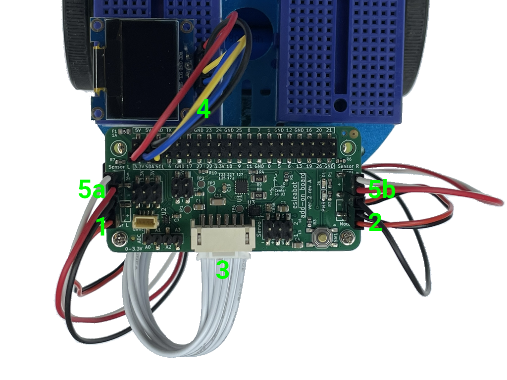
Make the following connections:
Connect the left motor to the add-on board at the location marked “Motor L”. The red wire should be on the + side.
Connect the right motor to the add-on board at the location marked “Motor R”. The red wire should be on the + side.
Connect the power board to the add-on board via the white or blue JST connector.
Connect the OLED screen as indicated:
SDA of the screen to SDA of the add-on board via a blue wire
SCL of the screen to SCL of the add-on board via a yellow wire
VCC of the screen to 3.3V of the add-on board via a red wire
GND of the screen to GND of the add-on board via a black wire
Connect each speed sensor to its location next to the motors on the add-on board as indicated:
5V of the speed sensor to the + of the add-on board via a long red wire
GND of the speed sensor to the - of the add-on board via a long black wire
OUT of the speed sensor to the S of the add-on board via a long white wire
Note
You can use the provided cable ties to keep the wires in place.
Step 25
Congratulations, your esieabot is now assembled. You now need to install its operating system to bring it to life. To do this, go to the section Installing esieabot. If you have a camera turret, you can also assemble it.