Add-on board
Since 2023, the esieabot has been equipped with a dedicated PCB to control its motors. It also adds new components such as an LED and an integrated button or an analog/digital converter.
Components
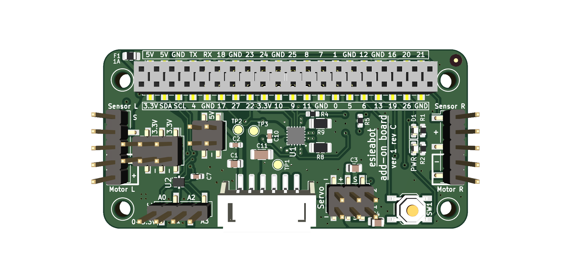
The esieabot add-on board is equipped with a DRV8411 motor controller from Texas Instrument (U1) as well as a TLA2024 analog-to-digital converter (U2). The ADC is connected to the Raspberry Pi I2C bus.
Add-on board version 2 also includes a 6-axis gyroscope and accelerometer TDK ICM-42670-P (U3) which is also connected to the Raspberry Pi I2C bus.
Connections

The connectors on the add-on board are as follows:
1: JST PH2.0 connector to the power board, for communication between the two boards and to transmit power to the rest of the robot.
2: Connector to the Raspberry Pi, connects to the GPIO with extension pins.
3: Connector for the motors, connects to the esieabot’s motors. The red wire to + and the black wire to -.
4: Connector for the speed sensors. Power to +, ground to -, and signal to S.
5: Connector for the servomotors. Power to +, ground to -, and signal to S.
6: Connector for the ADC. Analog sensors can be connected to this connector, with a voltage range between 0 and 3.3V.
7: 3.3V power strip, to be used for connecting other peripherals.
8: 5V power strip, to be used for connecting other peripherals.
Used pins
The add-on board connects a few components directly to the Raspberry Pi GPIOs as follows:
Button on GPIO 6
Blue LED on GPIO 26
Motor controls
- Motor 1 (left):
GPIO 23 for direction 1 (forward)
GPIO 25 for direction 2 (backward)
- Motor 2 (right):
GPIO 22 for direction 1 (forward)
GPIO 17 for direction 2 (backward)
Internal error state: GPIO 27 (read only), this GPIO is in logic HIGH state when all is well. It is in logic LOW state in the event of an error, such as motor controller temperature too high or overcurrent.
Servo motors on GPIO 13 (servo 1) and 18 (servo 2)
Speed sensors on GPIO 24 (left sensor) and 16 (right sensor)
Warning
On add-on board version 1 revision C and earlier models, the left speed sensor was using GPIO 4 instead of GPIO 24. This was changed in revision D. This is due to a default pull-up resistor on Raspberry Pi’s GPIO 4. If you own one of these previous release, you should manually plug your left speed sensor to GPIO 24.
Test the add-on board
You can launch a test program to check if the add-on board is working correctly. To run it, use the following command:
/esieabot/available/official/add-on-board-test.py
Then, follow the instructions on the screen. If you encounter any problems, refer to the troubleshooting guide.
Note
By default, the ADC will not be tested if you have not installed the
adafruit-circuitpython-tla202xpackage, which you can install with the following command:
pip install adafruit-circuitpython-tla202x --break-package-system