Assembling esieabot 2021 and 2022
Note
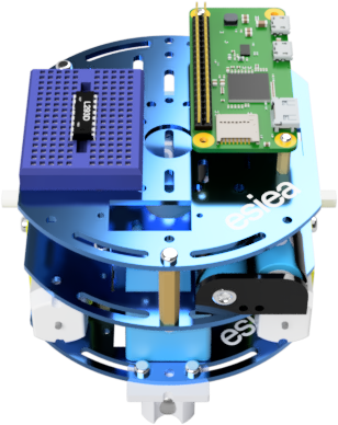
This is the manual for esieabot 2021 and 2022. This documentation is based on the manual distributed at the time to students. It is not intended to be used for other versions of the esieabot.
Inventory
Image |
Description |
Quantity |
|---|---|---|
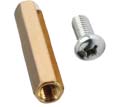
|
Big spacer with screw |
6 |
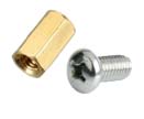
|
Small spacer with screw |
2 |
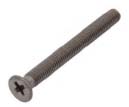
|
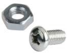
Big screw with nut |
4 |

|
Micro SD card with USB adapter |
1 |

|
Wired (2021) or wireless (2022) USB controller |
1 |
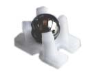
|
Free wheel |
1 |
|
Small screw with nut |
2 |
|
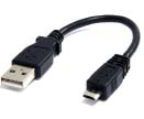
Micro USB cable |
1 |
|
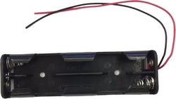
Battery holder |
1 |
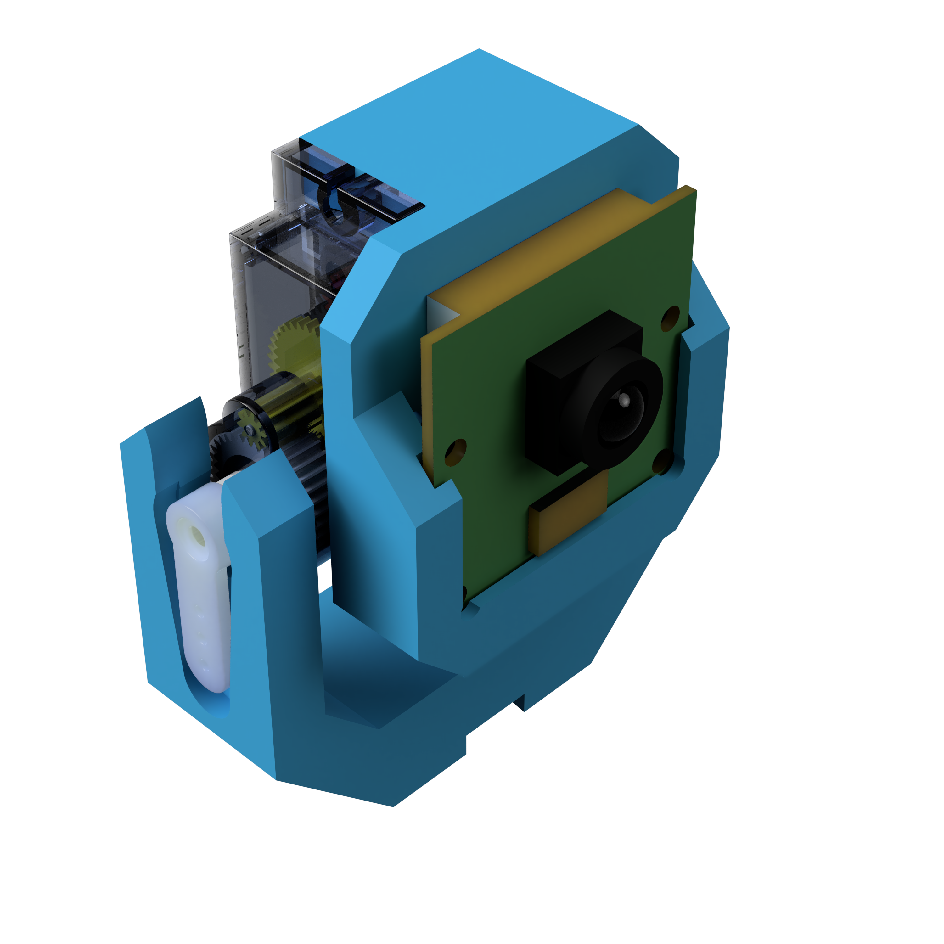
|
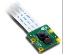
5Mpx camera |
1 |
|
USB battery |
1 |

|
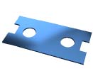
Metal frame |
3 |
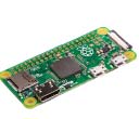
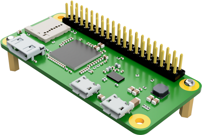
|
Raspberry Pi 0WH |
1 |
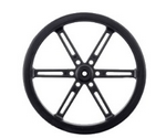
|
Wheel with tire and screw |
2 |
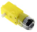
|
Motor |
2 |
|
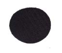
Scratchs M/F |
5 |
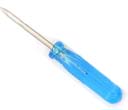
|
Small screwdriver |
1 |
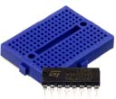
|
Small breadboard with L293D H-bridge |
1 |
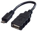
|
USB type A to micro USB adapter |
1 |
|
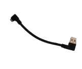
Angled micro USB cable |
1 |
|
Metal motor support |
2 |
|
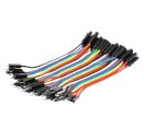
Wire M/M |
1 pack |
|
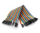
Wire M/F |
1 pack |

|
Rechargeable AA batteries |
4 |
Step 1
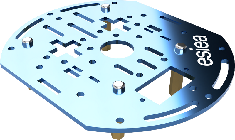
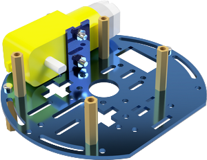
Take a plate and screw 4 big spacers underneath at the indicated places. This plate will be the central plate of the esieabot.
Warning
Pay attention to the orientation of the plate. The logo can help you to orientate yourself.
Step 2
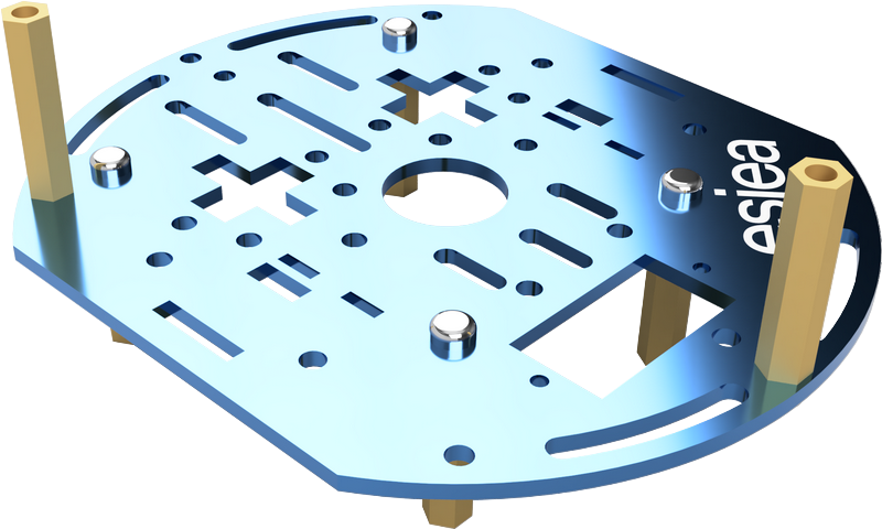
On the same plate, screw 2 large spacers on the top at the indicated locations.
Step 3
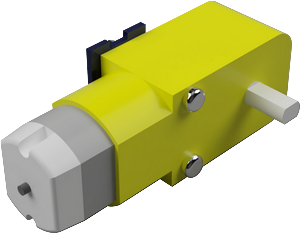
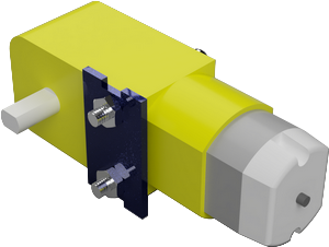
Take the two motors and screw in the metal motor supports with the large screws.
Warning
Attention, the placement of the supports has a direction to respect. There is a small deception in the form of a yellow cylinder on the motors. The metal bracket must be installed on the other side.
Step 4
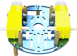
Position the motors on the central plate at the indicated locations. They will be fixed permanently afterwards.
Step 5
Take a new plate and screw the freewheel to the indicated place with the small screws. Then position and screw this new plate on the old one at the indicated place. The motors should now be fixed.
Step 6
Place the battery between the 2 motors. It must be able to hold by simple friction. If necessary, you can use a scratch.
Step 7
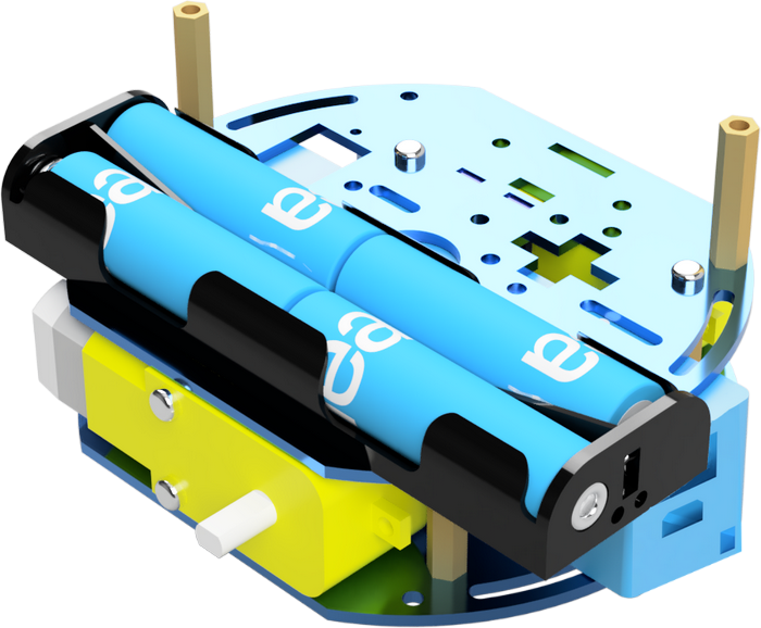
Take 2 male/female scratch pads and place them under the battery holder. Then glue the battery holder to the center plate where indicated.
Warning
You cannot charge your batteries while they are in the battery holder. You must absolutely remove them.
Step 8
Screw the small spacers on the Raspberry Pi at the indicated places.
Note
If your screws are too small, you can use plastic washers to adjust.
Step 9
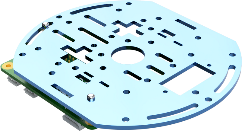
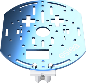
Take a new plate and screw the Raspberry Pi to the indicated place.
Step 10

On this new plate, stick the breadboard in the indicated place. Then screw the plate on the rest of the esieabot.
Step 11
If your H-bridge is not already in your breadboard, you can install it now, with the key on top of the image.
Step 12
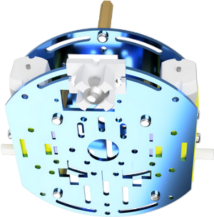
Screw the wheels with their tires on the indicated places.
Step 13
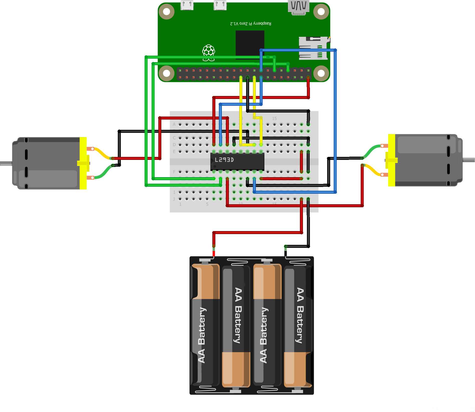
Connect the wires between the motors, the Raspberry Pi and the breadboard as shown.
Warning
Do not connect the batteries until you have checked that the rest of the connection is correct. You could destroy components otherwise.
Note
On the breadboard, the columns are connected to each other except in the middle where they are cut. So the location of the wires does not matter, as long as they are on the right column. Similarly, the color of the wires is not important. However, it is advisable to respect it in order to be able to diagnose potential problems with the support more quickly.
Step 14
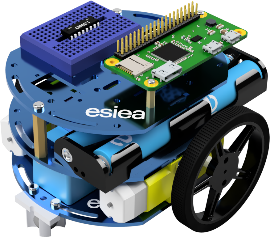
Congratulations, your esieabot is now assembled. Now you have to install its operating system to give it life. To do this, go to the Using an esieabot section. If you have a camera turret, you can also assemble it.