Assembling esieabot 2023
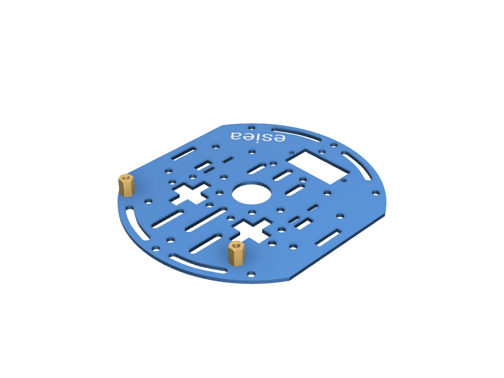
Step 1
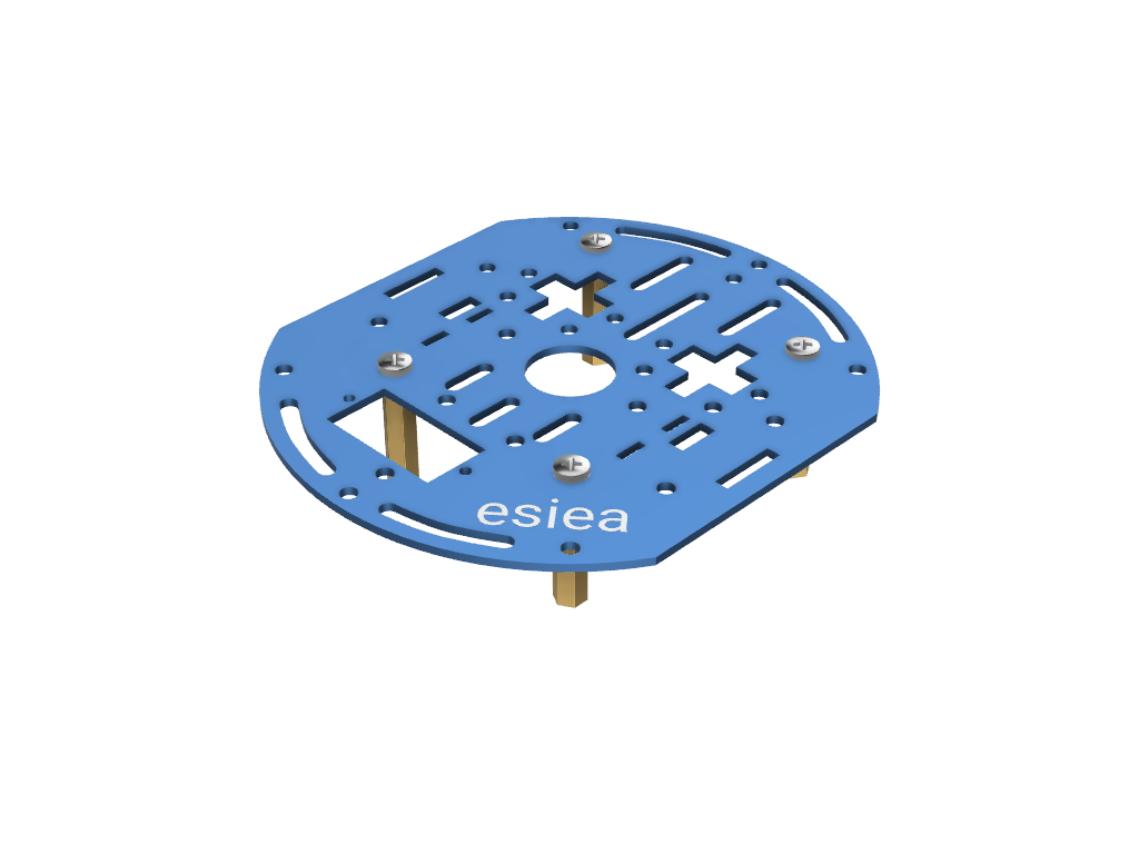
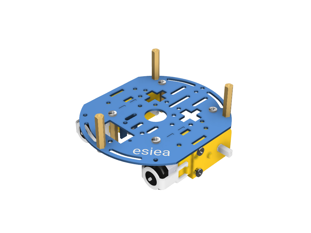
Take a plate and screw 4 large spacers underneath at the indicated locations. This plate will be the central plate of the esieabot.
Warning
Pay attention to the orientation of the plate. The logo can help you orient yourself.
Step 2
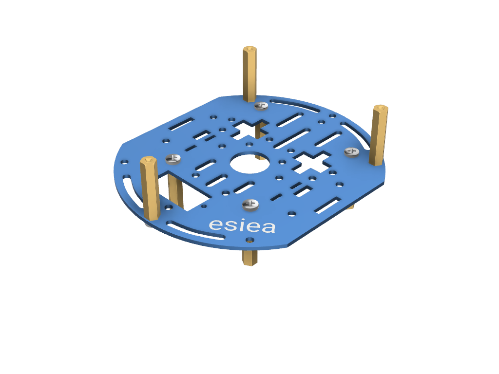
On the same plate, screw 3 large spacers on the top at the indicated locations.
Step 3
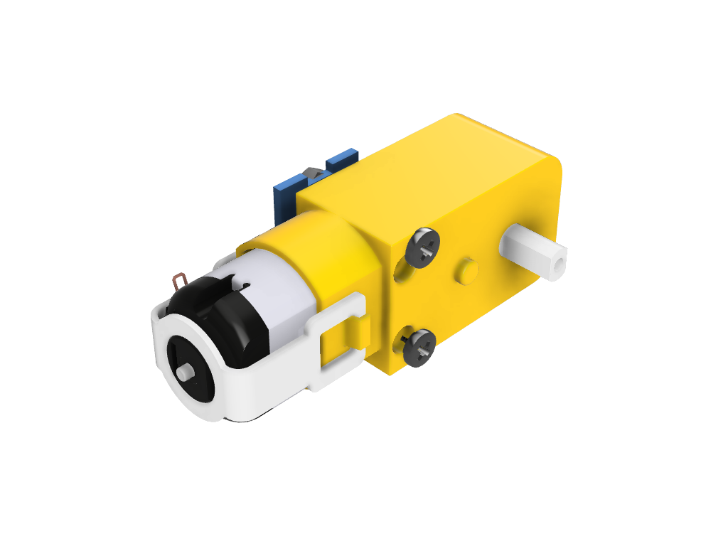
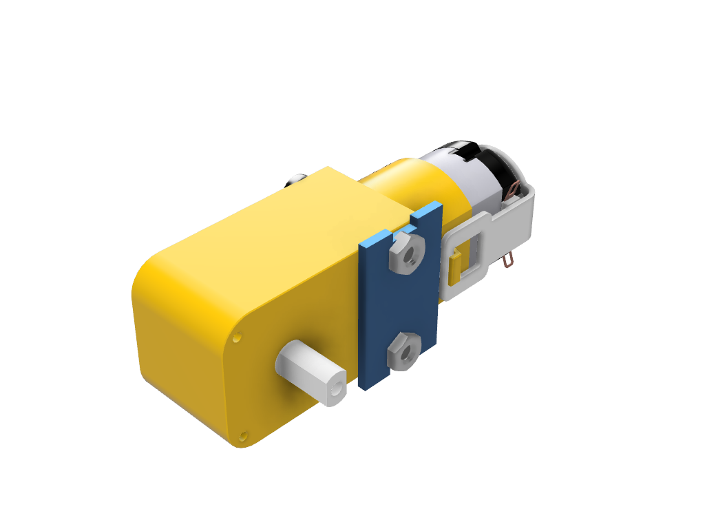
Take the two motors and screw the metal motor mounts with the large screws.
Warning
Be careful, the placement of the mounts has a specific orientation to follow. There is a small keying feature in the form of a yellow cylinder on the motors. The metal mount must be installed on the other side
Step 4
Position the motors on the central plate at the indicated locations. They will be permanently fixed later.
Step 5
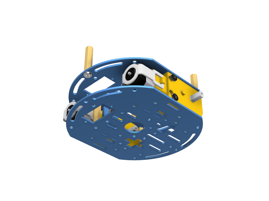
Take a new plate and screw it onto the old one at the indicated location. The motors should then be secured.
Step 6
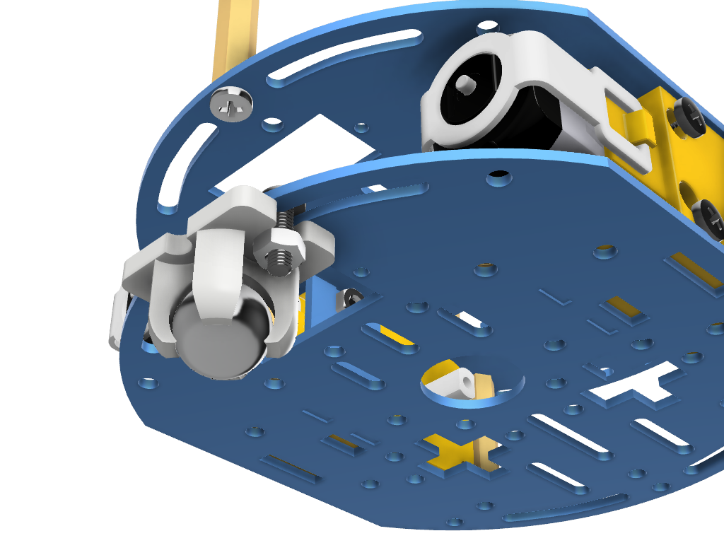
Screw the free wheel onto the new plate at the indicated location. It is easier to first position the screws without tightening them completely and then insert the wheel.
Step 7
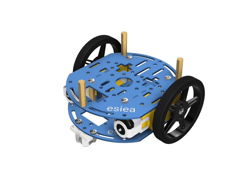
Screw the wheels and their tires onto the motors.
Step 8
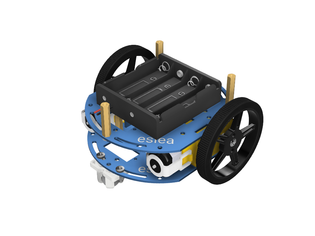
Position the battery holder in the middle of the esieabot using Velcro straps.
Warning
You cannot charge your batteries while they are in the battery holder. You must absolutely take them out.
Step 9
Take a new plate and screw small spacers at the indicated locations.
Step 10
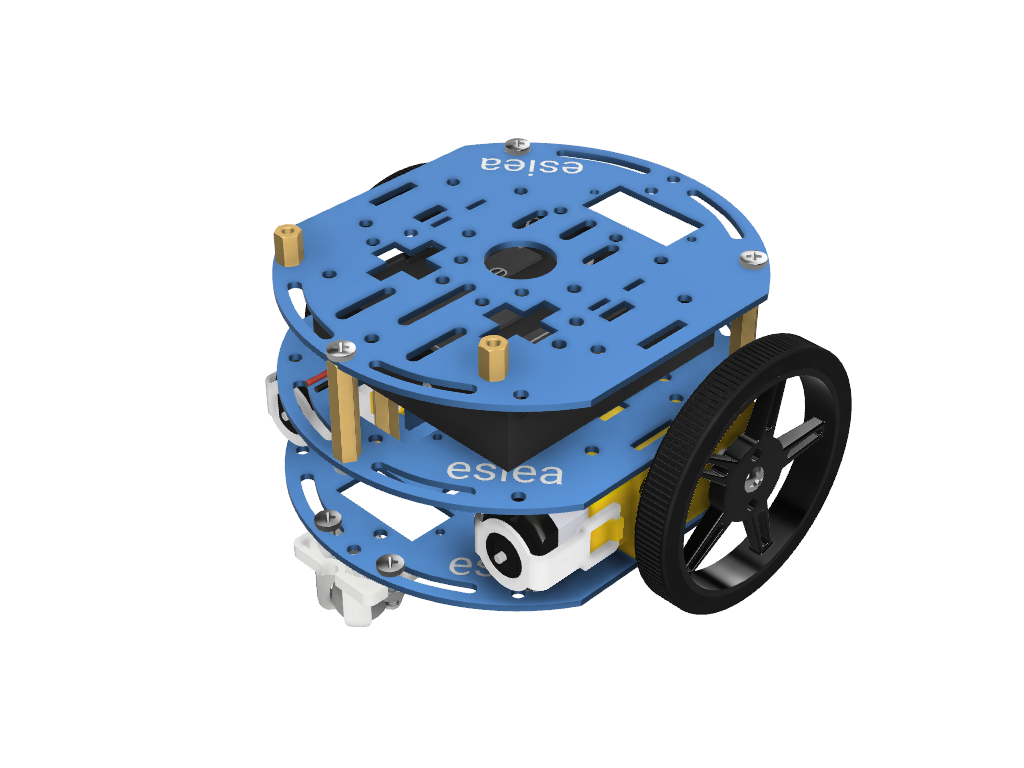
Screw this new plate above the esieabot.
Step 11
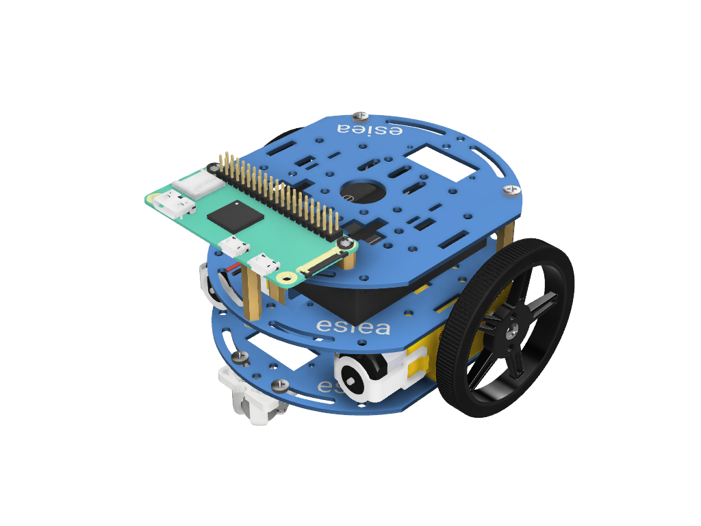
Screw the Raspberry Pi onto the small spacers screwed in step 9.
Step 12

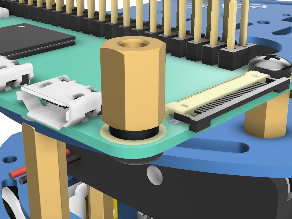
Screw small spacers onto the Raspberry Pi at the indicated locations, making sure to position a plastic washer as indicated.
Step 13
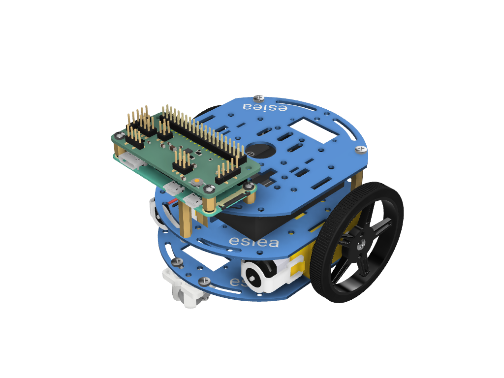
Position the add-on board on top of the Raspberry Pi and screw it.
Step 14
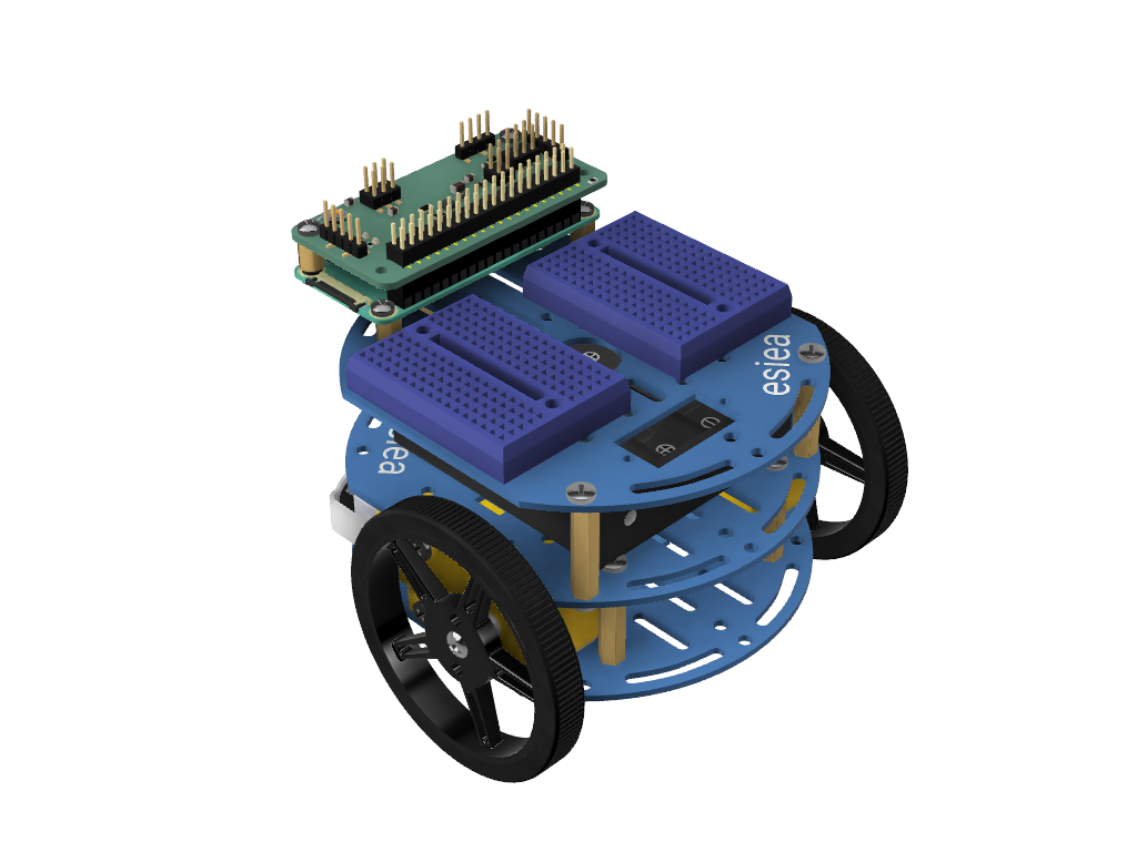
Position the 2 adhesive breadboards as indicated.
Step 15
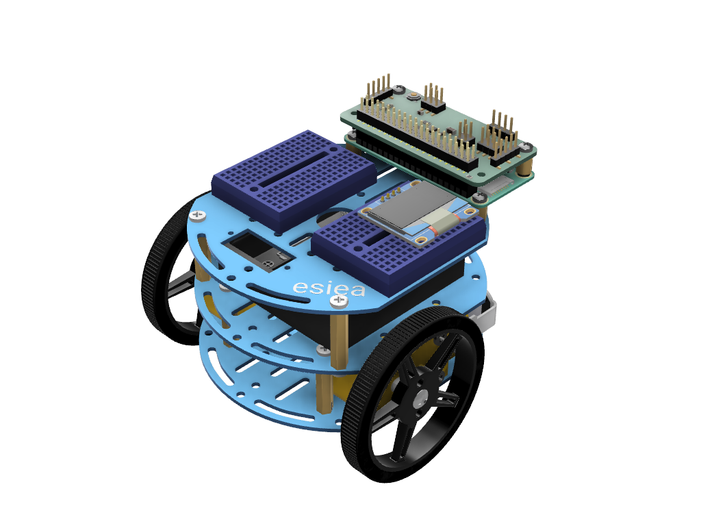
Connect the OLED screen to one of the breadboards as shown.
Warning
You must place the screen in the same orientation as in the picture
Step 16
Warning
Do not connect the batteries until you have verified that the rest of the wiring is correct. You may risk damaging components otherwise
Note
On the breadboard, the columns are connected to each other except in the middle where they are cut. The placement of the wires is therefore not important, as long as it is in the right column. Similarly, the color of the wires is not important. However, it is advisable to follow it to diagnose potential problems with the support more quickly
Make the following connections:
Connect the left motor to the add-on board at the “Motor L” marked location. The red wire should be on the + side.
Connect the right motor to the add-on board at the “Motor R” marked location. The red wire should be on the + side.
Connect the battery holder to the add-on board via the white JST connector.
Connect the OLED screen as follows:
Screen’s SDA to add-on board’s SDA via a blue wire
Screen’s SCL to add-on board’s SCL via a yellow wire
Screen’s VCC to add-on board’s 3.3V via a red wire
Screen’s GND to add-on board’s GND via a black wire
Step 17
Congratulations, your esieabot is now assembled. Now you have to install its operating system to give it life. To do this, go to the Using an esieabot section. If you have a camera turret, you can also assemble it.