Assembling esieabot 2020
Note
This is the manual for the 2020 esieabot, the very first esieabot distributed to students. This documentation is based on the very imperfect manual distributed at the time to students. It is not intended to be used for later versions of the esieabot.
Inventory
Image |
Description |
Quantity |
|---|---|---|
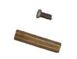
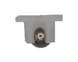
|
Big spacer with screws |
6 |
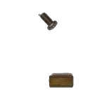
|
Little spacer with screws |
2 |
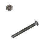
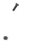
|
Big screw with nut |
4 |
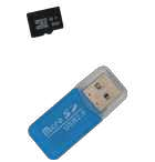
|
Micro SD card with USB adapter |
1 |

|
Wired USB controller |
1 |
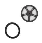
|
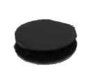
Free wheel |
1 |
|
Little screw with nut |
2 |
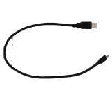
|
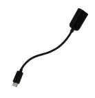
Micro USB cable |
1 |
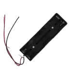
|
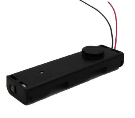
Battery holder |
1 |
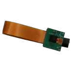
|
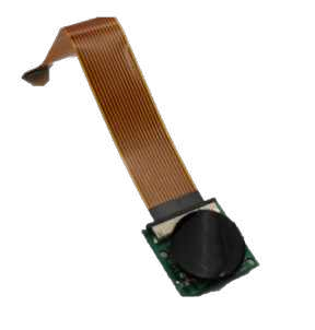
5Mpx camera |
1 |
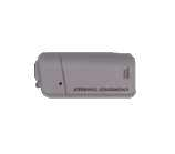
|
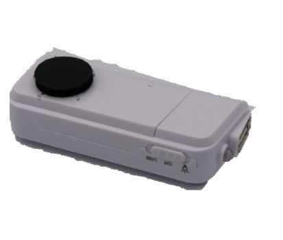
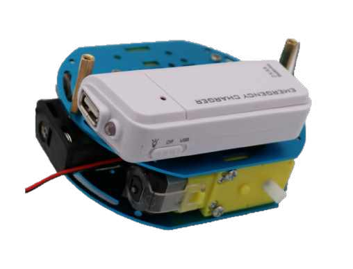
USB battery with AA battery |
1 |
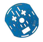
|
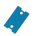
Metal frame |
3 |
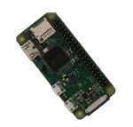
|
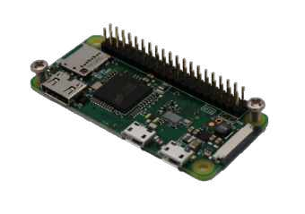
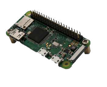
Raspberry Pi 0WH |
1 |
|
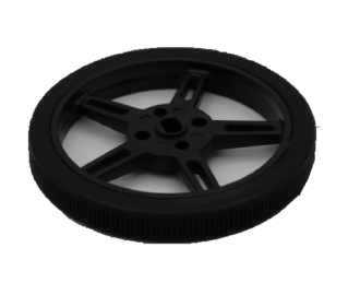
Wheel with tire and screw |
2 |
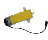
|
Motor |
2 |

|
Scratchs M/F |
5 |
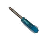
|
Small screwdriver |
1 |
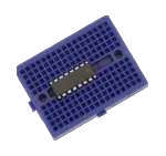
|
Small breadboard with L293D H-bridge |
1 |
|
USB type A to Micro USB adapter |
1 |
|
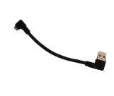
Angled micro USB cable |
1 |
|
Metal motor support |
2 |
|
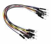
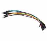
M/M wire |
1 pack |
|
M/F wire |
1 pack |

|
Common sense |
1 |
Etape 1
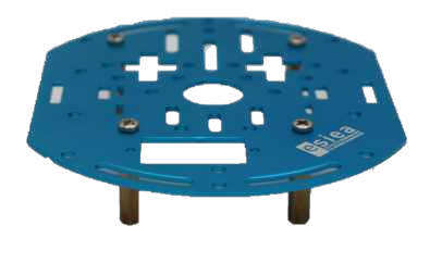
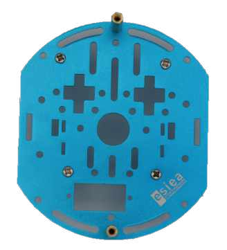
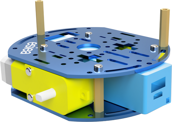
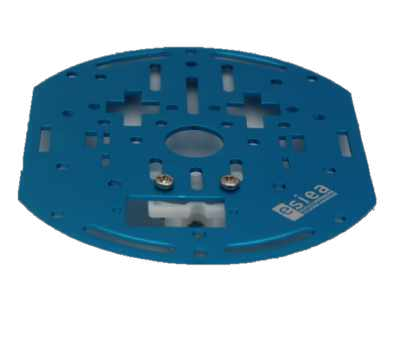
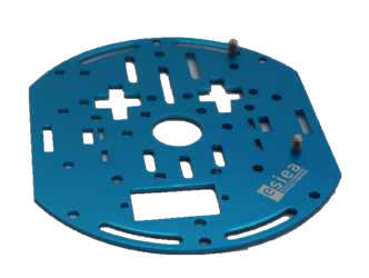
Take a plate and screw 4 large spacers underneath at the indicated places. This plate will be the central plate of the esieabot.
Warning
Pay attention to the orientation of the plate. The logo can help you to orientate yourself.
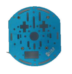
Step 2
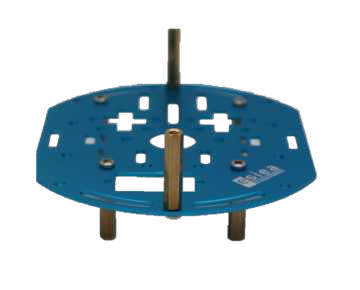
On the same plate, screw 2 large spacers on the top at the indicated locations.
Step 3
Take 2 male/female scratch pads and place them under the battery holder.
Step 4
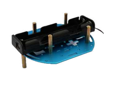
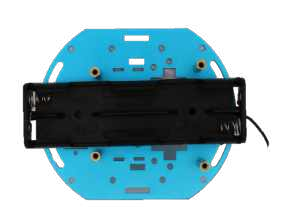
Glue the battery holder to the center plate at the indicated location.
Note
You can put your batteries in the battery holder now to facilitate the assembly.
Step 5
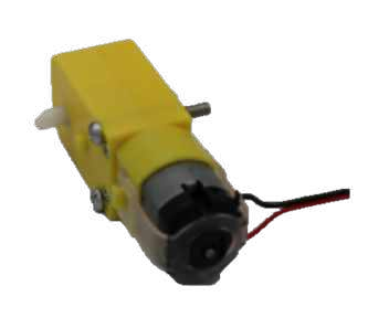
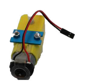
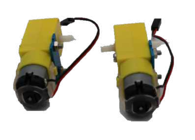
Take the two motors and screw in the metal motor supports with the large screws.
Warning
Attention, the placement of the supports has a direction to respect. There is a small deception in the form of a yellow cylinder on the motors. The metal bracket must be installed on the other side.
Step 6
Position the motors on the central plate at the indicated locations. They will be permanently fixed afterwards.
Step 7
Take a new plate and screw in the indicated place the free wheel with the small screws.
Step 8
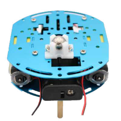
Position and screw this new plate on the old one at the indicated place. The motors should then be fixed.
Step 9
Take 2 male/female scratch pads and place them under the USB battery.
Step 10
Stick the USB battery on the plate at the indicated place.
Step 11
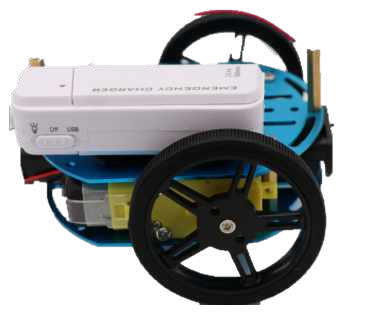
Screw the wheels with their tires on the indicated places.
Step 12
Screw the small spacers on the Raspberry Pi at the indicated places.
Note
If the holes are too small, you can take scissors to file it very lightly and make it bigger.
Step 13
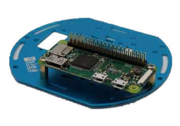
Take a new plate and screw the Raspberry Pi to the indicated place.
Step 14
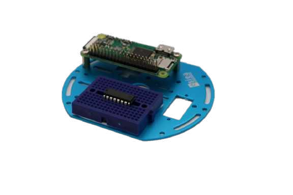
On this new plate, stick the breadboard with the H-bridge in the indicated place.
Step 15
Screw this plate to the rest of the robot at the indicated place.
Step 16
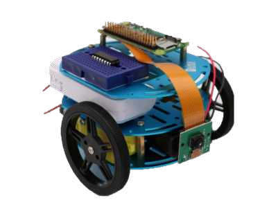
Take the camera and glue a male/female scratch pad to its back. Then glue it to the front of the esieabot.
Step 17
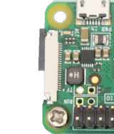
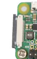
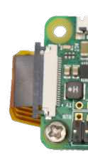
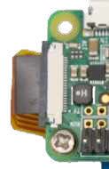
Attach the camera ribbon to the Raspberry Pi as shown.
Step 18
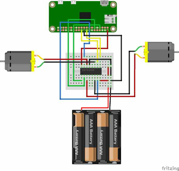
Connect the wires between the motors, the Raspberry Pi and the breadboard as shown.
Warning
Do not connect the batteries until you have checked that the rest of the connection is correct. You could destroy components otherwise.
Note
On the breadboard, the columns are connected to each other except in the middle where they are cut. So it doesn’t matter if the wires are impaled on the right column. Similarly, the color of the wires does not matter. However, it is advisable to respect it in order to be able to diagnose potential problems with the support more quickly.
Step 19
Connect the angled micro-USB cable between the USB battery and the PWR port of the Raspberry Pi. Connect the USB type A to micro USB adapter between the controller and the USB port of the Raspberry Pi.
Step 20
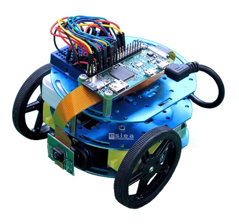
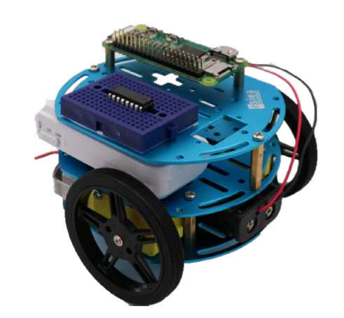
Congratulations your esieabot is now assembled. Now you have to install its operating system to give it life. To do this, go to the section Using an esieabot.