Python programming on esieabot
pigpiod
To program on the esieabot, we use pigpiod. pigpio is a library for controlling GPIOs. Unlike WiringPi, it is still maintained to this day. pigpiod is a way of using pigpio with a central service allowing several programs to be launched at once, without monopolizing the GPIOs.
This documentation is a condensed version of the official pigpiod documentation https://abyz.me.uk/rpi/pigpio/python.html.
Basics
When you run a program using pigpiod, it communicates with the pigpiod service in order to transmit its commands. Before launching a program, make sure that the service is running with the command systemctl status pigpiod. Several programs may be running at the same time. If they send contradictory commands, pigpiod will only take into account the last command received.
As on an Arduino, there are a multitude of GPIO pins that can be used. More information can be found in the Raspberry Pi documentation. A number of GPIOs are already in use on your esieabot for basic functions. Refer to your esieabot’s assembly manual or to add-on board documentation if you have one.
As on an Arduino, GPIOs can be used as input or output, to receive or send logic signals. On a Raspberry Pi, logic signals must be at 3.3V, not 5V. In all cases, at the start of the program, initialize the connection to the pigpiod service with this function:
import pigpio
import time # Not used in this example, but useful later

pi = pigpio.pi()

if not pi.connected:
    print("Can't connect to pigpiod")
    exit()
The pi variable then represents the esieabot entity. To interrupt the connection with the pigpiod service, use the following function at the end of the program:
pi.stop()
GPIO “Hello World!”: light an LED
First, connect the LED to an unused GPIO, for example GPIO 16. Don’t forget to connect a resistor in series to limit the current.
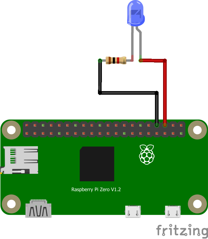
Next, define GPIO 16 as an output with the following function:
pi.set_mode(16, pigpio.OUTPUT) # Set GPIO 16 to output mode
Finally, you can turn it on and off with this simple loop:
while True:
    pi.write(16, 1) # Send a "HIGH" signal to GPIO 16 to turn it on
    time.sleep(1)
    pi.write(16, 0) # Send a "LOW" signal to GPIO 16 to turn it off
    time.sleep(1)
If everything’s connected correctly, you should have an LED flashing every second!
Using a push-button
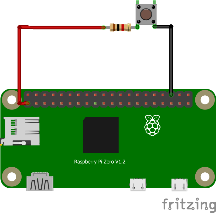
First of all, you need to connect the pushbutton to an unused GPIO, such as GPIO 16.
Warning
Pay attention to the direction of the pushbutton. Check with a multimeter if in doubt.
Note
In this situation, when the pushbutton is pressed, a 3.3V signal will be received by GPIO 16. Otherwise, nothing will be sent and GPIO 16 will be in an undefined state. To overcome this, we’re going to use the “PULL DOWN” mode. This means we’re going to tell the Raspberry Pi to “connect” GPIO 16 to an internal pull-up resistor connected to ground, to default GPIO 16 to a logic 0 and not to an uncertain electrical state. Thus, when the push-button is not pressed, a logical 0 will be obtained when trying to read the value of GPIO 16, since GPIO 16 will be connected to ground via this pull-up resistor.
To initialize the push-button, proceed as follows:
pi.set_mode(16, pigpio.INPUT) # Set GPIO 16 to input mode
pi.set_pull_up_down(16, pigpio.PUD_DOWN) # Enable pull-up resistor on GPIO 16
We then have two possible methods for reading the state of the pushbutton. Firstly, the “polling” method, which consists of reading the GPIO state in a loop to find out if there has been a change, or the “interrupt” method, which consists of monitoring the GPIO state in the background and executing a function as soon as it changes.
Warning
Regardless of the method used, pushbuttons can suffer a “bounce” effect, i.e. the signal may not be stable for a few moments after being physically pressed. To counter this, you can add an extra delay to ignore potential rapid changes.
Polling
while True:
    state = pi.read(16) # Read push-button state
    if state == 1: # If the GPIO has received a "HIGH" signal
        print("The push button on GPIO 16 is engaged")
    elif state == 0: # If the GPIO has received a "LOW" signal
        print("The push button on GPIO 16 is released")
    else: # Should not exist
        print("GPIO 16 is in an unknown state")
    time.sleep(1)
Interrupt
# Define a function, separate from the rest of the code
def my_function(gpio, level, tick):
    print("I was called because the state of the push button has changed")

pi.callback(16, pigpio.RISING_EDGE, my_function) # Create the callback, which will call the function
                                                 # "my_function" (without parentheses) when the state
                                                 # of GPIO 16 is on a rising edge
                                                 # (for example, when the pushbutton has just been pressed)

while True:
    print("Nothing happens in this loop.")
    print("But as I've created a callback, if the pushbutton is pressed, my_function() will be called.\n\n")
    time.sleep(1)
Using an H-bridge
The commands for using an H-bridge are the same as for controlling an LED, since the latter only needs to receive logic signals to switch a motor on and off. Refer to documentation of the H-bridge and assembly manual for the signals to be sent. If you have an add-on board, you should check its documentation.
Warning
Attention, the H-bridge model changes starting from the 2023 edition of the esieabot. Even though the operating principle remains the same, you should refer to the documentation of the add-on board for the signals to send.
If you only send basic logic signals (HIGH or LOW), your esieabot will only go at full speed in one direction or the other. To control the speed more precisely, you need to send PWM signals.
Using a servomotor
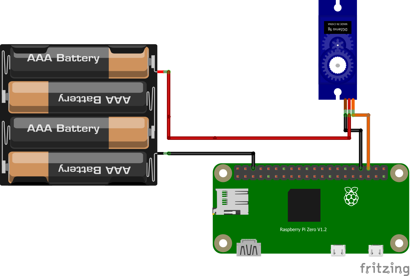
To use a servomotor, you need to send signals of very precise duration to communicate an angle setpoint. More information on servomotor documentation. With the pigpiod library, you can transmit an angle setpoint directly to a servomotor, without having to worry about the precise signals. Setpoints range from 500 to 2500. 0 disarms the servomotor. Any GPIO can be used as a signal source. For greater precision (to avoid “jitter” effects) it is possible to use the hardware PWM ports of Raspberry Pi.
Note
If you are using an add-on board (esieabot 2023 and later), you must use the dedicated servo connector, near the integrated button.
pi.set_mode(16, pigpio.OUTPUT) # Set GPIO 16 to output mode
pi.set_servo_pulsewidth(16, 500) # Set servo motor to minimum value
time.sleep(1)
pi.set_servo_pulsewidth(16, 1500) # Set servo motor to middle position
time.sleep(1)
pi.set_servo_pulsewidth(16, 2500) # Set servo motor to maximum position
time.sleep(1)
pi.set_servo_pulsewidth(16, 0) # Disarms servo motor
Sending a PWM signal
A PWM (Pulse Width Modulation) signal is used to control an electronic component as if it were controlled by an analog signal that varies in voltage. To do this, we’ll rapidly transmit HIGH and LOW signals with a bandwidth that varies according to the desired average voltage. With a Raspberry Pi, all GPIOs can be used to emit this kind of signal. In concrete terms, this makes it possible to vary the brightness of an LED or the speed of a DC motor.

Illustration PyroElectro, http://www.pyroelectro.com/tutorials/fading_led_pwm/theory.html
With pigpiod, we use the set_PWM_dutycycle() function to emit a PWM signal. The requested bandwidth must be between 0 and 255. 0 corresponds to off, 255 to on.
pi.set_mode(16, pigpio.OUTPUT) # Set GPIO 16 to output mode
pi.set_PWM_dutycycle(16, 0) # Produces an average voltage of 0V (as if sending a LOW signal)
time.sleep(1)
pi.set_PWM_dutycycle(16, 128) # Produces an average voltage of 1.65V (half of 3.3V)
time.sleep(1)
pi.set_PWM_dutycycle(16, 255) # Produces an average voltage of 3.3V (as if sending a HIGH signal)