C programming on esieabot
pigpiod
To program on the esieabot, we use pigpiod. pigpio is a library for controlling GPIOs. Unlike WiringPi, it is still maintained to this day. pigpiod is a way of using pigpio with a central service allowing several programs to be launched at once, without monopolizing the GPIOs.
This documentation is a condensed version of the official pigpiod documentation http://abyz.me.uk/rpi/pigpio/pdif2.html.
Compiling a program with pigpiod
gcc file.c -o executable -lpigpiod_if2
To compile a program using the pigpiod library, you need to add the -lpigpiod_if2 option to your gcc command.
#include <pigpiod_if2.h>
All that’s left is to add the library header to your code.
Basics
When you run a program using pigpiod, it communicates with the pigpiod service in order to transmit its commands. Before launching a program, make sure that the service is running with the command systemctl status pigpiod. Several programs may be running at the same time. If they send contradictory commands, pigpiod will only take into account the last command received.
As on an Arduino, there are a multitude of GPIO pins that can be used. More information can be found in the Raspberry Pi documentation. A number of GPIOs are already in use on your esieabot for basic functions. Refer to your esieabot’s assembly manual or to add-on board documentation if you have one.
As on an Arduino, GPIOs can be used as input or output, to receive or send logic signals. On a Raspberry Pi, logic signals must be at 3.3V, not 5V. In all cases, at the start of the program, initialize the connection to the pigpiod service with this function:
int pi = pigpio_start(NULL, NULL);

if (pi < 0) {
    printf("Can't connect to pigpiod");
    exit(-1);
}
The pi variable then represents the esieabot entity. To interrupt the connection with the pigpiod service, use the following function at the end of the program:
pigpio_stop(pi);
Note
In the following examples, include unistd.h to use the sleep() function.
Programming “like on an Arduino”
If you want to use a program structure similar to Arduino, you can use this basic code with the setup() and loop() functions:
#include <pigpiod_if2.h>

// Variable pi for pigpiod management
int pi;

void setup() {
    // TODO: Initialization of the pigpiod library
}

void loop() {
    // TODO: Main program loop
}

// Main function, do not touch
int main(int argc, char *argv[])
{
    setup(); // The setup function is called only once at the beginning
    while (1)
    {
        loop(); // The loop function is called in an infinite loop
    }
    return 0;
}
// End of main function
GPIO “Hello World!”: light an LED
First, connect the LED to an unused GPIO, for example GPIO 16. Don’t forget to connect a resistor in series to limit the current.
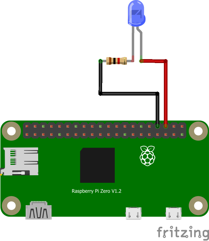
Next, define GPIO 16 as an output with the following function:
set_mode(pi, 16, PI_OUTPUT); // Set GPIO 16 to output mode
Finally, you can turn it on and off with this simple loop:
while(1) {
    gpio_write(pi, 16, PI_HIGH); // Send a "HIGH" signal to GPIO 16 to turn it on
    sleep(1);
    gpio_write(pi, 16, PI_LOW); // Send a "LOW" signal to GPIO16 to turn it off
    sleep(1);
}
If everything’s connected correctly, you should have an LED flashing every second!
Using a push-button
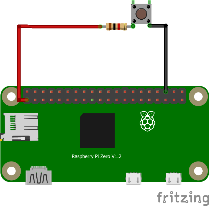
First of all, you need to connect the pushbutton to an unused GPIO, such as GPIO 16.
Warning
Pay attention to the direction of the pushbutton. Check with a multimeter if in doubt.
Note
In this situation, when the pushbutton is pressed, a 3.3V signal will be received by GPIO 16. Otherwise, nothing will be sent and GPIO 16 will be in an undefined state. To overcome this, we’re going to use the “PULL DOWN” mode. This means we’re going to tell the Raspberry Pi to “connect” GPIO 16 to an internal pull-down resistor connected to ground, to default GPIO 16 to a logic 0 and not to an uncertain electrical state. Thus, when the push-button is not pressed, a logical 0 will be obtained when trying to read the value of GPIO 16, since GPIO 16 will be connected to ground via this pull-down resistor.
To initialize the push-button, proceed as follows:
set_mode(pi, 16, PI_INPUT); // Set GPIO 16 to input mode
set_pull_up_down(pi, 16, PI_PUD_DOWN); // Enable pull-down resistor on GPIO 16
We then have two possible methods for reading the state of the pushbutton. Firstly, the “polling” method, which consists of reading the GPIO state in a loop to find out if there has been a change, or the “interrupt” method, which consists of monitoring the GPIO state in the background and executing a function as soon as it changes.
Warning
Regardless of the method used, pushbuttons can suffer a “bounce” effect, i.e. the signal may not be stable for a few moments after being physically pressed. To counter this, you can add an extra delay to ignore potential rapid changes.
Polling
while (1) {
    int state = gpio_read(pi, 16); // Read push-button state
    if (state == PI_HIGH) { // If the GPIO has received a "HIGH" signal
        printf("The push button on GPIO 16 is engaged");
    } else if (state == PI_LOW) { // If the GPIO has received a "LOW" signal
        printf("The push button on GPIO 16 is released");
    } else { // Should not exist
        printf("GPIO 16 is in an unknown state");
    }
    sleep(1);
}
Interrupt
void my_function() {
    printf("I was called because the state of the push button has changed");
}
callback(pi, 16, RISING_EDGE, my_function); // We create the callback, which will call the function
                                            // "my_function" (without parentheses) when the state
                                            // of GPIO 16 is on a rising edge
                                            // (for example, when the pushbutton has just been pressed)

while(1) {
    printf("Nothing happens in this loop;");
    printf("But as I've created a callback, if the pushbutton is pressed, my_function() will be called;");
    sleep(1);
}
Using an H-bridge
The commands for using an H-bridge are the same as for controlling an LED, since the latter only needs to receive logic signals to switch a motor on and off. Refer to documentation of the H-bridge and assembly manual for the signals to be sent. If you have an add-on board, you should check its documentation.
Warning
Attention, the H-bridge model changes starting from the 2023 edition of the esieabot. Even though the operating principle remains the same, you should refer to the documentation of the add-on board for the signals to send.
If you only send basic logic signals (HIGH or LOW), your esieabot will only go at full speed in one direction or the other. To control the speed more precisely, you need to send PWM signals.
Using a servomotor
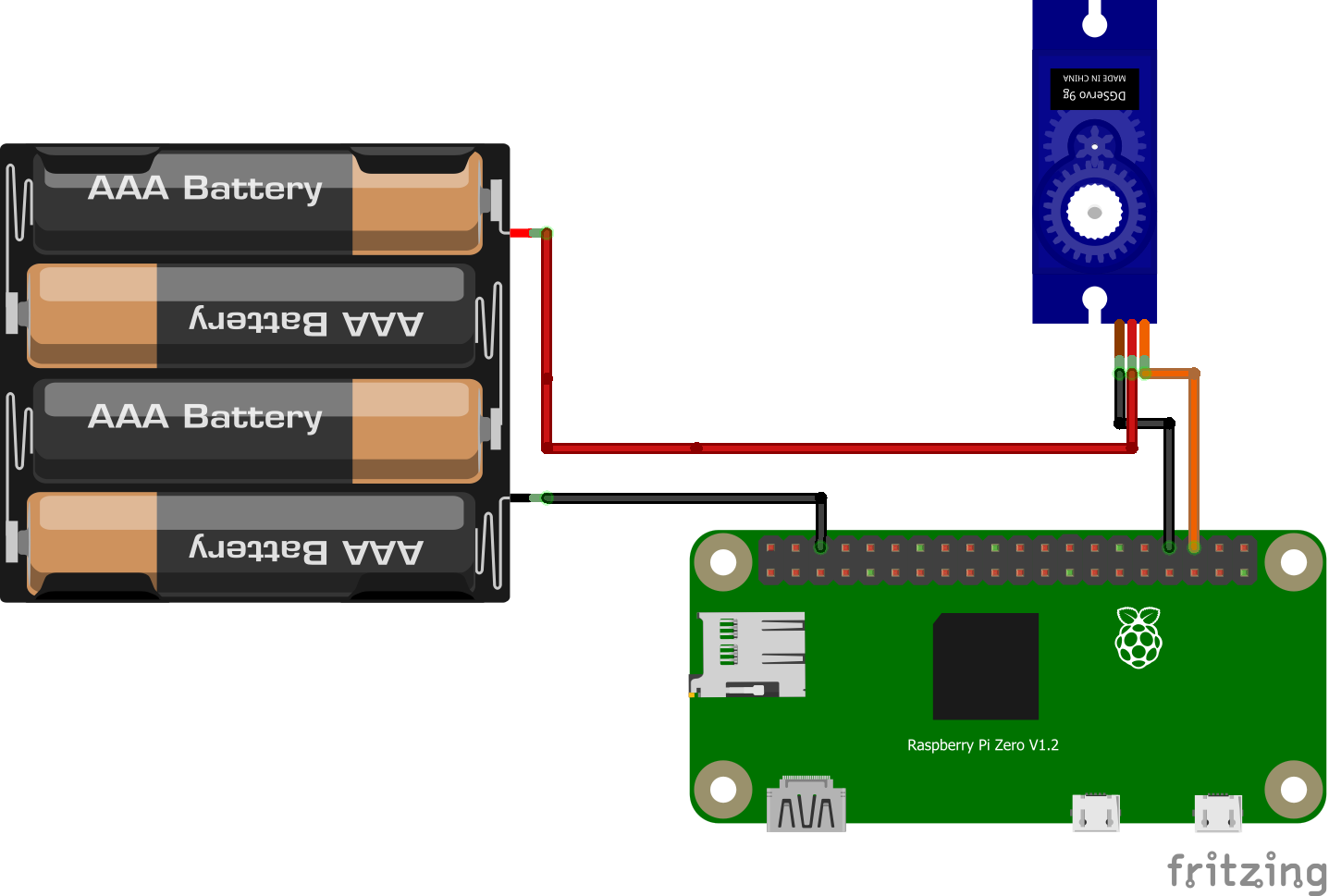
To use a servomotor, you need to send signals of very precise duration to communicate an angle setpoint. More information on servomotor documentation. With the pigpiod library, you can transmit an angle setpoint directly to a servomotor, without having to worry about the precise signals. Setpoints range from 500 to 2500. 0 disarms the servomotor. Any GPIO can be used as a signal source. For greater precision (to avoid “jitter” effects) it is possible to use the hardware PWM ports of Raspberry Pi.
Note
If you are using an add-on board (esieabot 2023 and later), you must use the dedicated servo connector, near the integrated button.
set_mode(pi, 16, PI_OUTPUT); // Set GPIO 16 to output mode
set_servo_pulsewidth(pi, 16, 500); // Set servo motor to minimum value
sleep(1);
set_servo_pulsewidth(pi, 16, 1500); // Set servo motor to middle position
sleep(1);
set_servo_pulsewidth(pi, 16, 2500); // Set servo motor to maximum position
sleep(1);
set_servo_pulsewidth(pi, 16, 0); // Disarms servo motor
Sending a PWM signal
A PWM (Pulse Width Modulation) signal is used to control an electronic component as if it were controlled by an analog signal that varies in voltage. To do this, we’ll rapidly transmit HIGH and LOW signals with a bandwidth that varies according to the desired average voltage. With a Raspberry Pi, all GPIOs can be used to emit this kind of signal. In concrete terms, this makes it possible to vary the brightness of an LED or the speed of a DC motor.
Illustration PyroElectro, http://www.pyroelectro.com/tutorials/fading_led_pwm/theory.html
With pigpiod, we use the set_PWM_dutycycle() function to emit a PWM signal. The requested bandwidth must be between 0 and 255. 0 corresponds to off, 255 to on.
set_mode(pi, 16, PI_OUTPUT); // Set GPIO 16 to output mode
set_PWM_dutycycle(pi, 16, 0); // Produces an average voltage of 0V (as if sending a LOW signal)
sleep(1);
set_PWM_dutycycle(pi, 16, 128); // Produces an average voltage of 1.65V (half of 3.3V)
sleep(1);
set_PWM_dutycycle(pi, 16, 255); // Produces an average voltage of 3.3V (as if sending a HIGH signal)
Using an ultrasonic distance sensor
See also
For wiring the HC-SR04 sensor, refer to the sensor documentation.
The HC-SR04 sensor operates in two steps: a 10 µs pulse is sent on the TRIG pin, then the duration for which the ECHO pin stays HIGH is measured. This duration, in microseconds, is proportional to the distance of the obstacle.
With pigpiod, gpio_trigger() is used to generate the trigger pulse, and callback() to precisely detect the rising and falling edges of the ECHO pin.
#include <pigpiod_if2.h>
#include <stdio.h>
#include <unistd.h>

// GPIO pin definitions
#define TRIG 10
#define ECHO 11

uint32_t tick_rise, tick_fall;

// This function is called automatically on each signal edge
void callback_echo(int pi, unsigned gpio, unsigned level, uint32_t tick) {
    if (level == 1) {
        tick_rise = tick;   // Rising edge: start of echo
    } else {
        tick_fall = tick;   // Falling edge: end of echo
    }
}

int main() {
    int pi = pigpio_start(NULL, NULL);
    if (pi < 0) return -1;

    set_mode(pi, TRIG, PI_OUTPUT);
    set_mode(pi, ECHO, PI_INPUT);
    gpio_write(pi, TRIG, 0);
    usleep(20000); // Wait 20 ms to stabilize the sensor

    // Register the callback on both edges of ECHO
    int cb_id = callback(pi, ECHO, EITHER_EDGE, callback_echo);

    // Send a 10 µs pulse on TRIG
    gpio_trigger(pi, TRIG, 10, 1);

    // Wait for the measurement to complete (30 ms max, ~5 m range)
    usleep(30000);

    // Compute the distance in centimeters
    uint32_t duration = tick_fall - tick_rise; // in microseconds
    float distance = (duration * 0.0343f) / 2.0f; // speed of sound
    printf("Distance: %.1f cm\n", distance);


    // End of program
    callback_cancel(cb_id);
    pigpio_stop(pi);
    return 0;
}
The duration variable represents the round-trip travel time of the ultrasonic signal. It is divided by 2 to get the one-way distance to the obstacle, and multiplied by 0.0343 (speed of sound in cm/µs).
Note
pigpiod tick values are 32-bit microsecond counters. For reliable measurements, do not use time() or clock(): always prefer the ticks provided in the callback.
Receiving signals from a controller
Note
This section applies equally to the USB controller included with your esieabot and to a Bluetooth controller or a virtual controller.
To receive signals from the controller in C language, we will use the native Linux joystick library. To do this, you must first include the following headers at the top of your program:
#include <stdio.h>
#include <stdlib.h>
#include <fcntl.h>
#include <unistd.h>
#include <linux/joystick.h>
Next, you need to open the USB controller file, which is generally located in the /dev/input/ folder and is usually named js0 or js1 depending on the number of controllers connected. To do this, use the following instructions:
int fd = open("/dev/input/js0", O_RDONLY);

if (fd < 0) {
    printf("Can't open joystick device\n");
    exit(-1);
}
In this example, the variable fd represents the USB controller. Next, you can use the read() function to read controller events. Events are stored in a data structure called js_event. This structure is already defined in the linux/joystick.h header. You must read events in a loop to be able to process controller signals in real time.
struct js_event event; // Structure to store controller events
while (1) { // Infinite loop
    if (read(fd, &event, sizeof(event)) > 0) { // Wait for a controller event and store it in the "event" variable
        // Processing of the controller event...
    }
}
To identify which button was pressed or which axis was moved, you must check the fields of the js_event structure:
type : indicates the type of event
Button pressed/released (
JS_EVENT_BUTTON)Axis movement (
JS_EVENT_AXIS)
number : indicates the number of the button or axis that was activated
value : indicates the value of the event
1: button pressed0: button releasedBetween
-32768and32767: value of an axis
So, if you want to display a message each time button number 0 is pressed, you can do it like this:
struct js_event event; // Structure to store controller events
while (1) { // Infinite loop
    if (read(fd, &event, sizeof(event)) > 0) { // Wait for a controller event and store it in the "event" variable
        if (event.type == JS_EVENT_BUTTON && event.number == 0 && event.value == 1) { // If button number 0 was pressed
            printf("Button number 0 was pressed\n");
        }
    }
}
libesieabot library
To make it easier to use certain complex tasks (such as speed control of motors via their speed sensors), you can use the libesieabot library which provides several advanced functions.
To install the library, run the following command:
sudo apt install libesieabot
To compile a program that uses the libesieabot library, you must add the option -lesieabot -lpigpiod_if2 -lm to your usual gcc command.
First, you must initialize the connection with the pigpiod service as before:
int pi = pigpio_start(NULL, NULL);

if (pi < 0) {
    printf("Can't connect to pigpiod\n");
    exit(-1);
}
The integrated motor controller allows fine control of a motor with proportional and integral speed regulation. To use it, you must first know the GPIOs used for forward, backward, and speed sensor, see the add-on board documentation if you have one. Then, you must initialize the motor controller with these GPIOs.
Warning
For the motor controller to work, you must have functional speed sensors. To test their operation, you can use the following command: /esieabot/available/official/add-on-board-test.py
Speeds and distances are expressed in slots. Your motors are equipped with encoder wheels with 20 slots. Here, we count the number of slot changes (open/closed). There are therefore 40 slot changes per wheel revolution. If you want your robot to move a precise distance, you must count the number of slots passed by the encoder wheels.
#define GPIO_FORWARD 23 // GPIO for forward command
#define GPIO_BACKWARD 25 // GPIO for backward command
#define GPIO_SENSOR 24 // GPIO for speed sensor
MotorController motor; // Create the motor controller object
MotorController_init(&motor, pi, GPIO_FORWARD, GPIO_BACKWARD, GPIO_SENSOR); // Initialize the motor controller
Then you must set the following parameters to adjust the behavior of the motor controller:
MotorController_setStartPower(&motor, 110);
float kp = 4.0f; // Recommended values for the PI controller
float ki = 2.0f;
MotorController_setController(&motor, kp, ki);
The motor controller is now ready to use. To move forward, use the following function:
float speed = 60.f; // Target speed in slots per second
MotorController_setTargetSpeed(&motor, speed);
To apply the target speed, you must call the following function in an infinite loop. If you do not, the motor controller will not be able to adjust the motor speed according to the speed measured by the sensor.
while (1) { // Infinite program loop
    // ... other possible processing ...
    MotorController_update(&motor);
}
If you want to make the motor go backward, just call the following function:
If you want to stop the motor, just call the following function:
MotorController_stop(&motor);
If you want your robot to move forward a precise distance, you can use the following function which requires prior initialization of each motor controller:
drive(&motor_left, &motor_right, slot_count, speed);
Warning
Warning, this function is blocking, meaning the program will not continue until the robot has traveled the requested distance.
Note
If you want your robot to go backward, you must call the MotorController_setBackward() as seen previously.
If you want your robot to turn in place by a precise angle, you can use the following function:
turn(&motor_left, &motor_right, slot_count, speed);
Warning
Warning, this function is blocking, meaning the program will not continue until the robot has traveled the requested distance.
Note
If you want your robot to turn left, you must set a positive slot count. If you want your robot to turn right, you must set a negative slot count.